Timing chart of parallel output, Timing chart of parallel output -38 – KEYENCE DV-90 User Manual
Page 98
4-38
E DV-90-IM
4
Ba
si
c
Func
tions
4-7 2-Point Verification Function
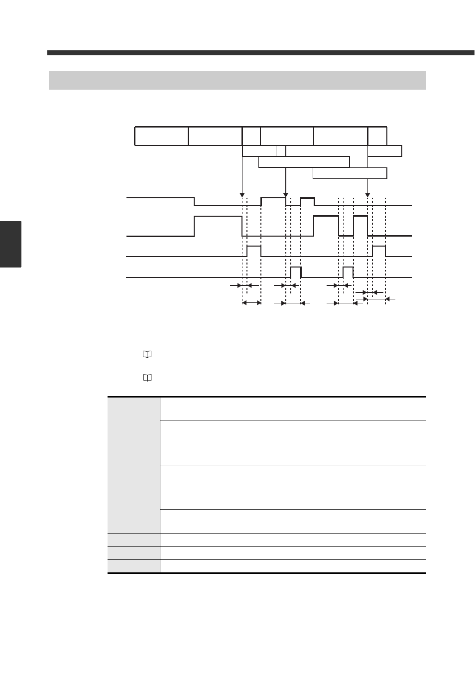
Timing Chart of Parallel Output
After reading the data, execute parallel output at the following timing:
The output form of OUT1 to 12 can be selected from bit, binary or BCD in the “Verification menu”.
➀...........Output ON time: Specify this in “Out ON time” in the I/O setting menu.
(
Refer to 6-11) (It can be set between 10 ms and 2550 ms. The factory setting is 500 ms.)
➁...........Output delay time: Specify this in “Out Delay” in the I/O setting menu.
(
Refer to 6-11) (It can be set between 0 ms and 255 ms. The factory setting is 5 ms.)
OUT1 to 12
• Only OUT9 to 12 turn ON while waiting for the First reading.
Only OUT5 to 8 turn ON while waiting for the Second reading.
• At Verify OK of the Second reading, OUT1 to 12 of the output numbers (1-900)
corresponding to the matched preset number turn ON.
(When the parallel output form is set to “Bit output”, OUT1 to 12 turn OFF with output
numbers over 13. The factory setting is “Bit output”.)
• When Verify NG occurs, OUT1 to 12 turn ON at output number 999.
• At Verify NG of the First reading, OUT1 to 12 turn ON at output number 998 as a Select
Master NG.
(When the parallel output form is set to “Bit output”, all turn OFF.)
• When a reading error occurs, OUT1 to 12 turn ON at output number 997.
(When the parallel output form is set to “Bit output”, all turn OFF.)
OK
Turns ON when Verify OK is output.
NG
Turns ON at Verify NG and Select Master NG.
READ_ERR
READ_ERRTurns ON when a reading error occurs.
OUT9 to 12
OUT5 to 8
OK
NG
Reading state
First data
reading
Second data
reading
First data
reading
Second data
reading
Verify OK
Verify OK
Select Master NG/Read_Error
Verify NG/Read_Error
q
q
q
q
w
w
w
w