KEYENCE DV-90 User Manual
Page 134
6-10
E DV-90-IM
6
Setti
ng
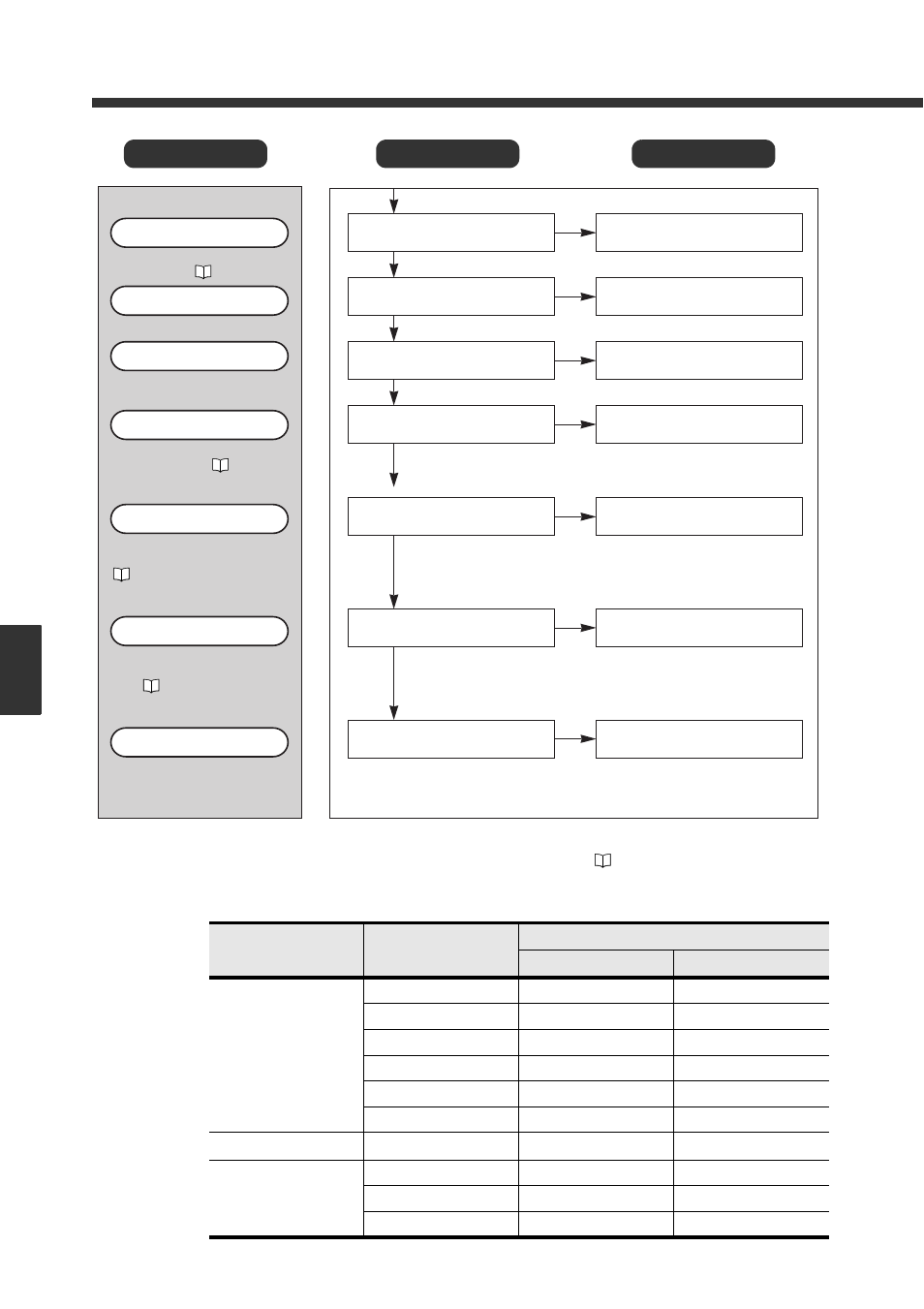
6-2 Setting Items of the DV-90
Setting Item LCD Display Selection Item
* When “Auto” is selected for the communication settings, the communication settings of the code
reader connected to PORT1/2 are automatically detected. (
Refer to 2-5)
** When “Default” is selected for the communication settings, the default values of the communica-
tion settings corresponding to the specified connected unit are displayed. Refer to the table below.
Connected Unit Setting
Type
Default Communication Setting
Baud rate
Data format
Code Reader
TYPE-A
9600bit/s
7e1
TYPE-B
9600bit/s
7e1
TYPE-C
9600bit/s
8n1
TYPE-D
9600bit/s
7e1
TYPE-E
115200bit/s
8e1
Others
9600bit/s
7e1
PC
-
9600bit/s
7e1
PLC Link
KEYENCE KV
9600bit/s
8e1
MELSEC
9600bit/s
8o1
SYSMAC
9600bit/s
7e2
0 : O F F
0 : O F F
1 : O N
: 0 ~ 1 0 0 %
( I n i t i a l V a l u e 5 0 % )
0 : O F F
0 : O F F
1 : O N
: 0 0 0 0 ~ 9 9 0 0
(Initial Value 0000)
1 6 Q u a l i t y
2 1 R T S / C T S
0 : O F F
0 : O F F
1 : O N
18 Read Error Check
0 : O F F
0 : O F F
1 : O N
3 2 P L C T i m e A r e a
: 0 0 0 0
3 1 D M A d d r e s s
: 0 0 ~ 3 1
(Initial Value 00)
: 0 0
3 3 P L C U n i t I D
: 5 0 %
1 7 Q u a l i t y L e v e l
ON/OFF of the read quality check
function is set. ( Refer to 5-14)
Read quality check function
Read quality threshold is set.
Read quality threshold
The function to be output when a
read error occurs is set.
Read error check
The RTS/CTS protocol is set (when the
PC is connected). ( Refer to 8-4)
It is displayed when “PORT2 Unit”
is set to “PC”.
RTS/CTS protocol
The DM head address is set (when
connected to the PLC link).
( Refer to 9-4)
It is displayed when “PORT2 Unit”
is set to “PLC Link”.
DM head address
ON/OFF of the PLC trigger notice
is set (when connected to the PLC
link). ( Refer to 9-8)
It is displayed when “PORT2 Unit”
is set to “PLC Link”.
PLC trigger notice area
The unit ID number of the PLC is set.
It is displayed when the PLC type
is “SYSMAC” or “MELSEC”.
PLC unit ID