KEYENCE DV-90 User Manual
Page 212
9-12
E DV-90-IM
9
PLC Link
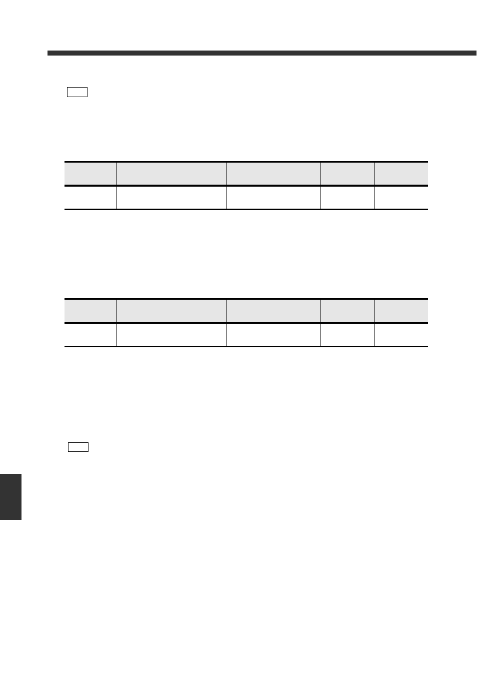
DM that detects the occurrence of a reset
• “1” is written when the DV-90 starts up.
The occurrence of a power reset in the DV-90 can be checked through this.
When a power reset has occurred in the DV-90, implement the necessary action to initialize the
DM.
• After confirmation, set it to “0” again.
DM that releases the interlock
• This DM reports to the DV-90 the release of the interlocks of the Verification OK output, Verifi-
cation NG output, and Read error output. For details on the interlock function, refer to page 4-11.
• When you want to release the interlock of these outputs, write “1” in “X+14”. Whether or not the
outputs are interlocked can be checked in “X+17 Operation Status Check Area”.
When the interlock is released, “0” is written in “X+14”.
Note
• If you follow the preceding steps, “X+11” becomes “0” while the active record is being
changed.
Since the active record is being changed when “X+11” is “0”, be sure to control the code
reader connected to the DV-90 so that it does not execute the reading operation.
DM
Description
Data description
Writing from
the DV-90
Writing from
the PLC
X+13
Reset Occurrence Detection Flag
0: No reset
1: Reset occurred
Yes
(0
→1)
Yes
(1
→0)
DM
Description
Data description
Writing from
the DV-90
Writing from
the PLC
X+14
Interlock Release Notice Flag
0: Interlock not released
1: Interlock released
Yes
(1
→0)
Yes
(0
→1)
Note
• Do not attempt to release the interlocks at once by writing “1” in “X+14” beforehand. Doing
so may result in incorrect manipulation of the data.
• The interlock release input from the I/O terminal can also be used at the same time. How-
ever, it is not recommended since it may cause a gap in controlling the programming of
the PLC.