KEYENCE DV-90 User Manual
Page 60
3-26
3
C
on
necti
ons
and
M
ounti
ng
E DV-90-IM
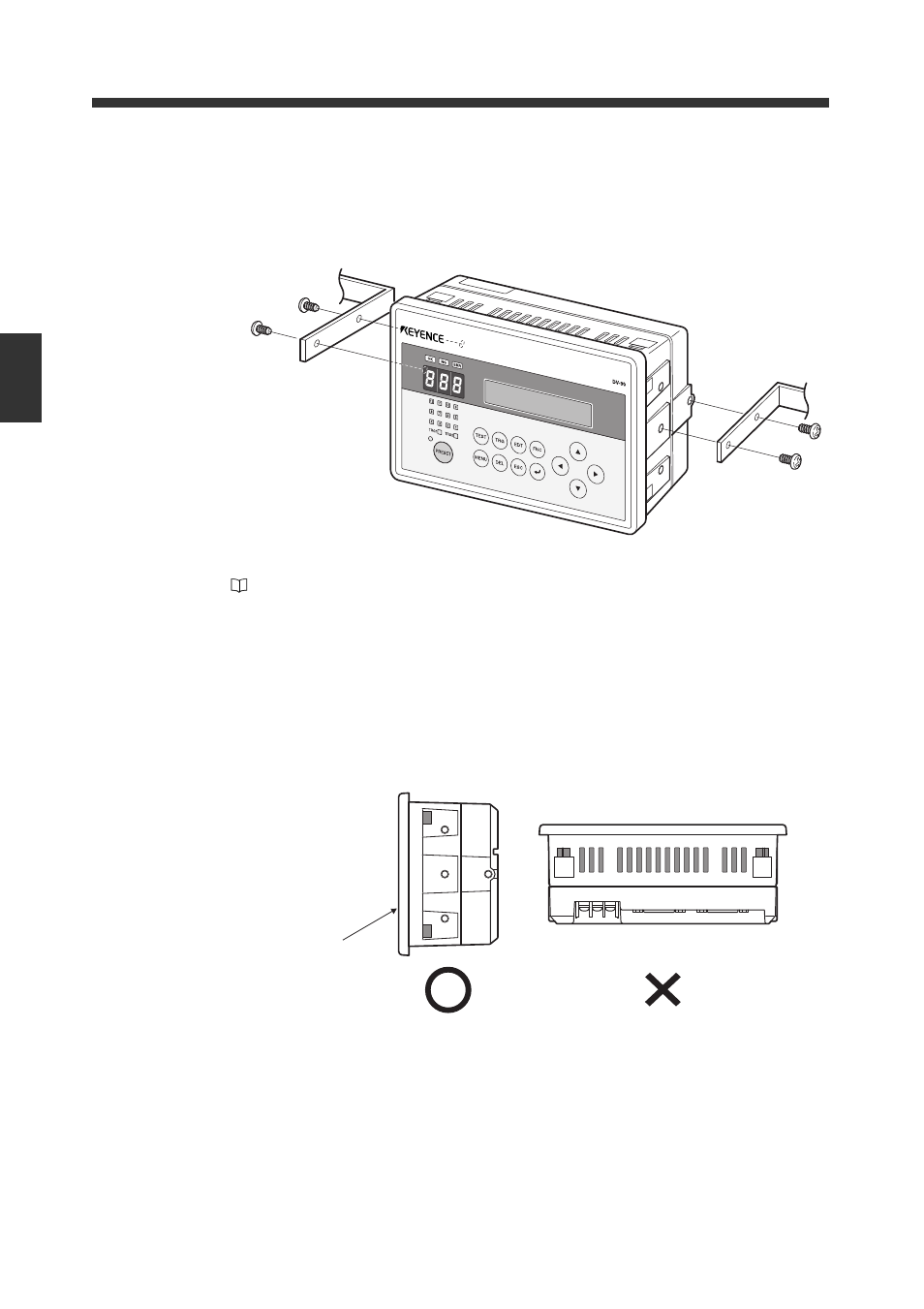
Mounting procedure using the mounting screws
When not installing the DV-90 on a panel, install the DV-90 by using the screw holes on its
sides.
The screw holes on the DV-90 are not threaded. Use the supplied M4 tapping screws for
installation.
• For the dimensions of the screw holes and their locations, refer to the outer dimensions
(
Appendix 3).
• The thickness of the bracket which the DV-90 is mounted should be between 2.0 and
2.3 mm.
Restrictions on the mounting orientation
The DV-90 is designed for panel mounting. Install the DV-90 in the orientation where the panel sur-
face is vertical against the ground. Do not keep the DV-90 placed with the panel facing up, down, or
tilted.
Panel surface
See also other documents in the category KEYENCE Sensors:
- LR-TB2000 Series (12 pages)
- LR-TB5000 Series (12 pages)
- LR-ZB250AN/AP (4 pages)
- LR-ZB250AN/P (3 pages)
- LR-ZBxN/P Series (3 pages)
- LR-ZBxxB (3 pages)
- OP-85135 (1 page)
- PZ-G Series (2 pages)
- PZ-V/M (2 pages)
- PS-N10 Series (12 pages)
- PX-10 (10 pages)
- CZ-V21A(P) (10 pages)
- CZ-K1(P) (8 pages)
- CZ-V1 (8 pages)
- FS-N10 Series (6 pages)
- FS-N10 Series (116 pages)
- FS-N15CN (1 page)
- FU-93(Z) (2 pages)
- FU-V Series (2 pages)
- FS-V30 (6 pages)
- FU-A40 (1 page)
- NU/FS-N Series (16 pages)
- FS-V33(P) (8 pages)
- FS-V21 (4 pages)
- FS-V22 (4 pages)
- FS-V11(P) (4 pages)
- FS-V1(P) (4 pages)
- LV-N10 Series (112 pages)
- LV-N10 Series (12 pages)
- LV-S62 (1 page)
- OP-84350 (1 page)
- LV-SA (10 pages)
- LV-SB (12 pages)
- OP-87305 (1 page)
- LV Series (10 pages)
- LV-B102 (1 page)
- EV-108M(U) (1 page)
- EZ Series (1 page)
- EM Series (1 page)
- ES-M1(P) (3 pages)
- EX-V Series (120 pages)
- EX-500(W) Series (16 pages)
- GV Series (10 pages)
- IA Series (8 pages)
- LB-1000(W) (24 pages)