Timing chart for parallel output, Interlock function – KEYENCE DV-90 User Manual
Page 71
4-11
4
E DV-90-IM
Ba
si
c
Func
tions
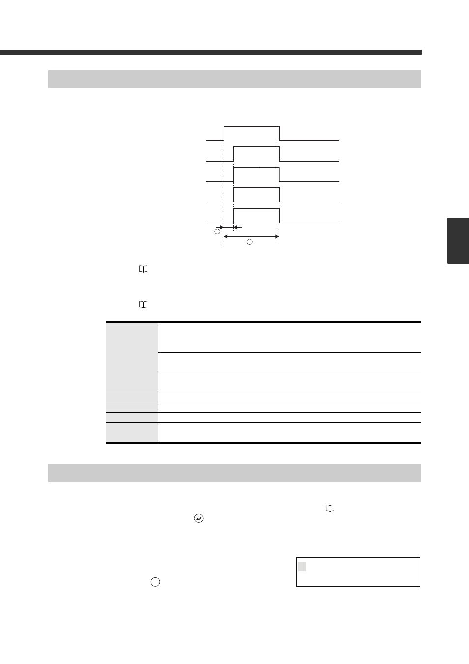
Timing Chart for Parallel Output
After reading the data, execute parallel output at the following timing:
The output form of OUT1 to 12 can be selected from bit, binary or BCD in the “Verification menu”
➀.........Output ON time: Specify this in “Out ON time” in the I/O setting menu.
(
Refer to 6-11) (It can be set between 10 ms and 2550 ms.) The factory setting is 500
ms.
➁ .........Output delay time: Specify this in “Out Delay” in the I/O setting menu.
(
Refer to 6-11) (It can be set between 0 ms and 255 ms.) The factory setting is 5 ms.
Interlock Function
With the interlock function, the DV-90 can be locked so as not to perform when Verify OK, Verify
NG, or a read error occurs.
The lock status can be cancelled by turning on the UNLOCK input (
Refer to 3-4) on the I/O
terminal or by pressing the
key.
How to configure the interlock function
1
Move to the setting mode.
Press the
key.
OUT1 to 12
• Outputs representing the matched record (Preset 1-900) are turned ON.
(When the parallel output form is set to “Bit output”, OUT1 to 12 are turned OFF with
output numbers over 13. The default output format is “Bit output”.)
• When Verify NG occurs, outputs representing “999” (NG and Verify NG) are turned ON.
ALL outputs are turned OFF when Bit output format is selected (default).
• When a read error occurs, outputs representing “997” (Read Error) are turned ON.
ALL outputs are turned OFF when Bit output format is selected (default).
OK
Turns ON when Verify OK is output.
NG
Turns ON when Verify NG is output.
READ_ERR
Turns ON when a read error occurs (Only when the read error check is set).
QUALITY
Turns ON when Read Quality NG occurs. However, it is not turned on when a read error
occurs.
OUT1~12
OK
NG
READ_ERR
QUALITY
1
2
2
V e r i f y
M a i n
1
MENU