KEYENCE DV-90 User Manual
Page 214
9-14
E DV-90-IM
9
PLC Link
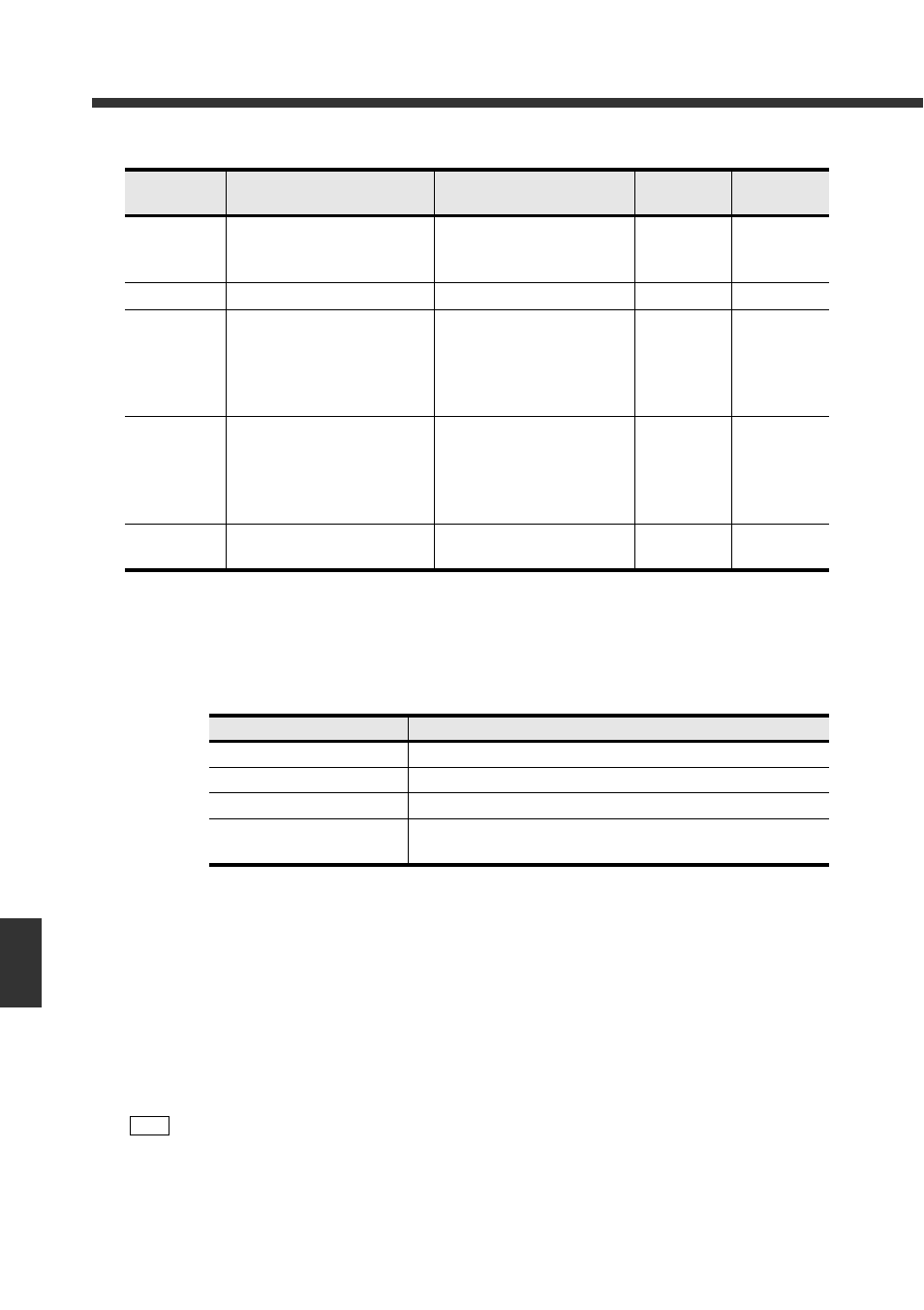
DMs in which various data is written
• All data shown above is written in binary code.
For the timing of when each type of data is written, refer to page 9-17.
• The current read number is written in “X+18”.
The read number to be generated varies depending on the “Verify Type” as shown in the
following list.
• “X+19 Verification count value Check Area” can be used only when “Counter” in “Verify” is set
to “ON”.
• “X+22 Read quality judgment Check Area” can be used only when “Read Quality Check” in
“PORT1” is set to “ON”.
Note that “Read Quality Check” cannot be used when “Verify Type” is “Verify Step”, “Verify
3Points-A”, or “Verify 3Points-B”.
• The values of “999: Verify NG”, “998: Selected Master Verify NG”, and “997: Read Error” can
be changed on the setup software. Refer to page 7-15 for details.
DM
Description
Data description
Writing from
the DV-90
Writing from
the PLC
X+18
Read State Number Check Area
1: First data reading
2: Second data reading
3: Third data reading
Yes No
X+19
Verify Count Value Check Area
0 to 65535
Yes No
X+20
Record Number Check Area
1 to 900: Record number
0: Verify Step OK
999: Verify NG
998: Selected Master Verify NG
997: Read Error
Yes No
X+21
Output Number Check Area
1 to 900: Output number
0: Verify Step OK
999: Verify NG
998: Selected Master Verify NG
997: Read Error
Yes No
X+22
Read Quality Check Area
0: Read Quality OK
1: Read Quality NG
Yes No
Verify Type
Read number to be generated
Verify Normal
1 only
Verify Active
1 only
Verify Step, Verify 2 points
1 and 2
Verify 3points-A, Verify
3points-B
1, 2 and 3
Note
When using the MELSEC Series, a value of “X+19” exceeding 32767 is recognized as a neg-
ative value.