Wiring the input terminals, Wiring the input terminals -4 – KEYENCE DV-90 User Manual
Page 38
3-4
3
C
on
necti
ons
and
M
ounti
ng
E DV-90-IM
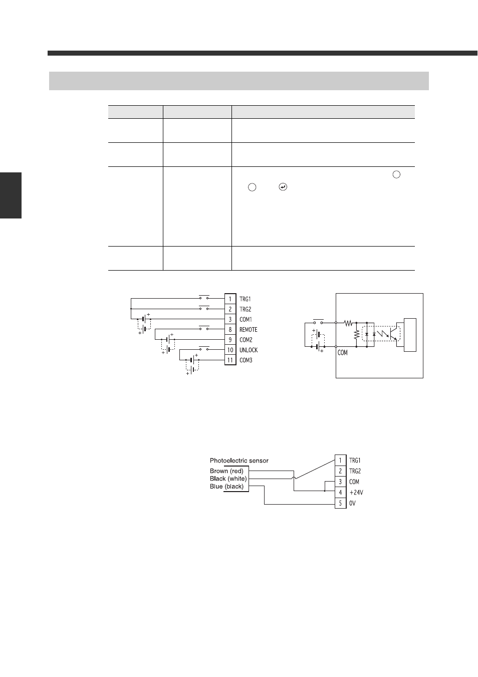
Wiring the Input Terminals
Connection diagram Circuit diagram
Wiring with a Keyence photoelectric sensor (Trigger input 1)
Pin label
Name
Description
TRG1
Trigger input 1
Inputs a trigger signal to the code reader connected to
PORT1.
TRG2
Trigger input 2
Inputs a trigger signal to the code reader connected to
PORT2.
REMOTE
Remote input
Performs the same key operation as the DV-90. Either
key,
key or
key can be assigned.
When the REMOTE input is turned on for exactly the length
of time indicated by the input constant (10 ms), the same
performance as when the assigned key is pressed once is
generated.
Refer to page 6-11 for the setting procedure.
UNLOCK
Unlock input
Cancels the interlock in the verification mode.
Refer to page 4-11 for details.
PRESET
ESC
10 to 26 VDC
* The COM terminals are insulated from each other.
* The 24V DC power output of the terminal block can be
used for the input power.
Input
Internal cir
cuit
• Input rated voltage : 10 to 26 V DC
• Maximum OFF current : 1.0 mA
(NPN)