KEYENCE DV-90 User Manual
Page 210
9-10
E DV-90-IM
9
PLC Link
DMs that report to the PLC that the data writing is completed
• “X+08 to +10” are the DMs that report to the PLC that new data has been written in the PLC.
The program in the PLC can check for new data being written by constantly monitoring these
DMs.
• “X+08 Data Write Process Method Notice Area” is the area in which the processing method for
writing data can be selected. The usage of areas “X+09 and +10” changes according to whether
“0: Real-time processing” or “1: Sequence processing” is selected.
• “1” is written in “X+09 Data Write Complete Check Flag” the moment new data is written. After
confirming that “X+09” has changed to “1”, be sure to set it to “0” again.
• “X+10 Data Write Enabled Notice Flag” is the flag that allows new data to be written. “X+10”
becomes valid only when “1: Sequence processing” is selected for “X+08 Data Write Process
Method Notice Area”.
Only when “X+10” is “1” does the DV-90 write the new data. When “X+10” is “0”, the new data
is not written, but is stored in the DV-90 send buffer instead.
• For the usages of “X+08 to +10”, refer to “Real-time processing” or “Sequence processing”
described below.
(Real-time processing)
➀Write “0” in “X+08” before starting an operation, and select “Real-time processing”.
➁“1” is written in “X+09” at the time the new data is written in “Y*+00…” of “X+18 to +22”.
The timing of when data is written varies depending on the “Verify Type” currently being used.
Refer to page 9-17 for details.
➂After confirming that “X+09” has changed to “1”, be sure to set it to “0” again.
➃Have the program manipulate the new data written in “Y*+00…” in “X+18 to +22”.
➄When the time between readings of the connected code reader is shorter than the communication
on the PLC link, the data that cannot be written in the PLC is stored in the DV-90 send buffer
(stores up to 64 data). The stored transmission data is written as soon as data write is enabled.
When no more space is available in the send buffer, the DV-90 displays the error screen “Snd
Buffer Over”, clears all the data in the send buffer, and then stops operation. Press the [ESC] key
to recover.
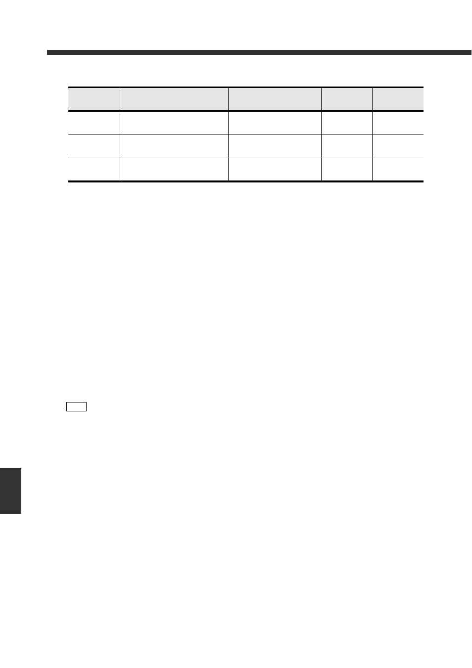
DM
Description
Data description
Writing from
the DV-90
Writing from
the PLC
X+08
Data Write Process Method Notice
Area
0: Real-time processing
1: Sequence processing
No Yes
X+09
Data Write Complete Check Flag
0: Data write not complete
1: Data write complete
Yes
(0
→1)
Yes
(1
→0)
X+10
Data Write Enabled Notice Flag
0: Data write disabled
1: Data write enabled
Yes
(1
→0)
Yes
(0
→1)
Note
• The DV-90 reads “X+08” at the same time that “1: Work start” is written in “X+00”. Changes
cannot be made during operation.