2 typical motion profiles, Synchronous cross cutter, Typical motion profiles -3 – Lenze EVS93xx CrossCutter User Manual
Page 17: Cross cutter, Features of the "cross cutter" prepared solution
Cross Cutter
Features of the "Cross Cutter" prepared solution
Prepared Solution Servo PLC / ECSxA 1.1 EN
2-3
2.2.2
Typical motion profiles
Synchronous cross cutter
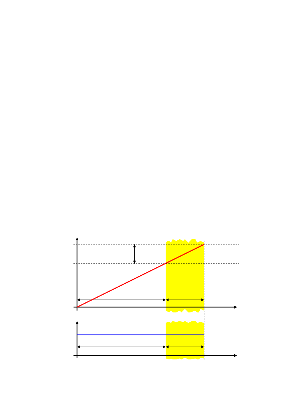
The following diagrams illustrate the position characteristic (red) and the speed signal (blue) for
three different cutting lengths in a cross-cutter application:
Concepts:
y
max
=
Final value of the slave (cross-cutter knife) motion profile. This value will vary
depending on the number of knives on the cross-cutter drum.
For example: 1 knife => y
max
= 360°; 2 knives => y
max
= 180°
y
end
=
Final value of the asynchronous motion phase and start of the synchronous motion
phase.
sync
end
y
y
y
−
=
max
y
sync
=
Indicates the cutting angle. In this range the knife is synchronised with the line
speed.
t
asynchron
= During this time the cross-cutter knife can move out of synchronism with the line
speed.
t
synchron
= During this time the movement of the cross-cutter knife is synchronised with the line
speed.
t
cycle
=
Duration of a cross-cutter revolution
t
1
=
Start of the synchronous phase
a) Synchronous cutting length
(cutting length x
max
= cutting circle circumference of knife drum x
circumference
)
y
t
y
max
V
t
V
synchron
t
1
t
cycle
t
1
t
cycle
t
asynchron
t
asynchron
t
synchron
t
synchron
cutting
phase
cutting angle y
sync
y
end