4 setting the parameters of the prepared solution, 1 control/status interface with master control, Control interface – Lenze EVS93xx CrossCutter User Manual
Page 115: Control/status interface with master control -101, Cross cutter
Cross Cutter
Installing and starting up the "CrossCutter" prepared solution
Prepared Solution Servo PLC / ECSxA 1.1 EN
3-101
3.4
Setting the parameters of the prepared solution
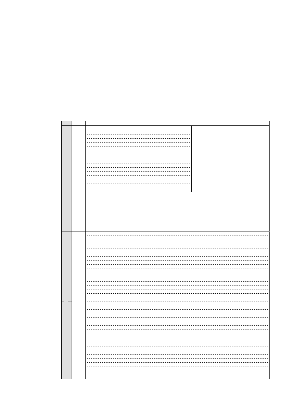
3.4.1 Control/Status interface with master control
In the parameterisable variant, the control and status interface is preconfigured. An overview of
signal assignment and the options for reconfiguring (multiplexing) the control/status signals
appears below.
Control
interface
Meaning
Bit 00: Dependent on the setting in code C4000/000
Bit 01: Dependent on the setting in code C4000/000
Bit 02: Dependent on the setting in code C4000/000
Bit 03: Dependent on the setting in code C4000/000
Bit 04: Dependent on the setting in code C4000/000
Bit 05: Dependent on the setting in code C4000/000
Bit 06: Dependent on the setting in code C4000/000
Bit 07: Dependent on the setting in code C4000/000
C4000/000 = 0:
The
DCTRL_wAIF1Ctrl and
DCTRL_wCAN1Ctrl system
variables are always set to zero.
Bit 08: Dependent on the setting in code C4000/000
Bit 09: Dependent on the setting in code C4000/000
Bit 00: Dependent on the setting in code C4000/000
Bit 11: Dependent on the setting in code C4000/000
Bit 12: Dependent on the setting in code C4000/000
Bit 13: Dependent on the setting in code C4000/000
Bit 14: Dependent on the setting in code C4000/000
Wo
rd
0
System control
word
Bit 15: Dependent on the setting in code C4000/000
C4000/000 = 1, 2, 3:
C4000/000 = 4, 5, 6:
The drive control word is copied to
DCTRL_wCAN1Ctrl;
DCTRL_wAIF1Ctrl is set to zero.
The drive control word is copied to
DCTRL_wAIF1Ctrl;
DCTRL_wCAN1Ctrl is set to zero.
Wo
rd
1
Data word 1
Control word: Selection of operating mode:
1: Cutting
mode
2: Reject
mode
3: Test
mode
4: Asynch.
Mode
Bit 00: Start/stop homing, only in conjunction with controller enable (g_bHomingStart)
Bit 01: Set home position (g_bHomePositionSet)
Bit 02
Reset home position (g_bHomePositionReset)
Bit 03
Manual jog in positive direction (CW) (g_bManualJogPos)
Bit 04: Manual jog in negative direction (CCW) (g_bManualJogNeg)
Bit 05: Perform positioning (g_bMotionStart)
Bit 06: Activate external user error (g_bExtUserError)
Bit 07: Reset error (g_bErrorReset)
Bit 08: Inhibit controller (g_bControllerInhibit)
Bit 09: QSP (g_bUserQuickstop)
Bit 10: Activate the DFIN test signal to simulate the DFIN signal (g_bUseTestsignal)
Bit 11: Reset the cutting counter for cutting operation (g_bResetCuttingProfileCounter)
Bit 12: Reset the cutting counter for reject operation (g_bResetRejectProfileCounter)
Bit 13: Reset the cutting counter for test operation (g_bResetTestProfileCounter)
Bit 14: Start and stop selected cross-cutter operating mode (g_bStartStopOperation).
Wo
rd
2
Bit 15: Activate the variable to accept a newly calculated cutting length immediately and work with the new cutting length
(g_bWorkWithNewCuttingLength)
Bit 16: Activate the variable to accept a newly calculated reject length immediately and work with the new cutting length
(g_bWorkWithNewRejectLength)
Bit 17: Activate the variable to accept a newly calculated test length immediately and work with the new cutting length
(g_bWorkWithNewTestLength)
Bit 18: Activate X trimming and switch from the calculated mark sensor distance to the mark sensor distance specified by X trimming
(g_bUseXPositionTrimming)
Bit 19: Key this input to perform X trimming in a positive direction at the set speed (g_bXAxisTrimmingPosDirection).
Bit 20: Key this input to perform X trimming in a negative direction at the set speed (g_bXAxisTrimmingNegDirection).
Bit 21: Enable print-mark synchronisation (g_bXTpEnable)
Bit 22: Enable ramp generator for print-mark synchronisation (g_bRfgXTpEnable)
Bit 23: Reset counter for number of print marks located outside the window (g_bResetCounterTPOutOfWindow)
Bit 24: Abort cross-cutter operation (g_bAbordCrossCutter)
Bit 25: Execute X trimming absolute positioning (g_bLoadSetXAxisTrimmingTPPos)
Bit 26: (not assigned)
Bit 27: (not assigned)
Bit 28: (not assigned)
Bit 29: (not assigned)
Bit 30: (not assigned)
Wo
rd
3
Applicat
ion cont
rol word
Bit 31: (not assigned)