Cross cutter – Lenze EVS93xx CrossCutter User Manual
Page 124
Cross Cutter
Installing and starting up the "CrossCutter" prepared solution
Prepared Solution Servo PLC / ECSxA 1.1 EN
3-110
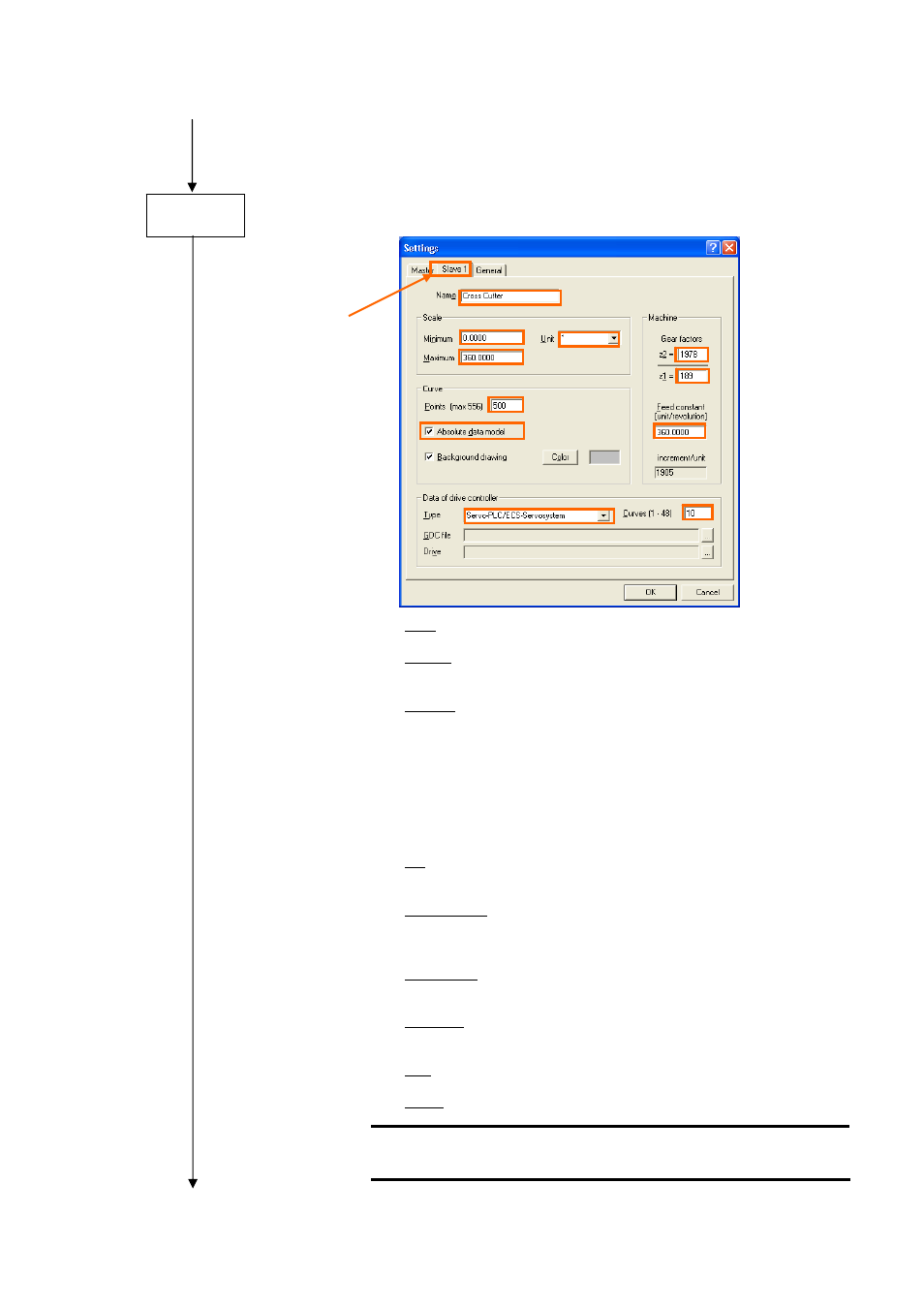
Click the Slave 1 tab to make the settings for the drive axis on the rotary cross cutter:
Name:
Name of the cam axis (in the example: "CrossCutter")
Minimum:
Minimum position in the cross-cutter cycle, must
always be set to 0.0000[°]
Maximum:
Maximum position y
max
in the cross-cutter cycle:
This value is dependent on the mechanical engineering of
theknife drum and may exhibit the following values:
y
max
= 360.0000[°]:
1 knife per knife drum
y
max
= 180.0000[°]:
2 knives per knife drum
y
max
= 120.0000[°]:
3 knives per knife drum
etc.
y
max
= 60.0000[°]:
6 knives per knife drum
Unit:
Unit in which the feed motion of thecross cutter is scaled
(in the example: 1[s_unit] = 1[°])
Gearbox factors:
Entry indicating the gearbox factors of the cross-cutter
drive (with numerator and denominator indicated
separately) (in the example: z
2
: z
1
= 1978 : 189)
Feed constant:
Entry indicating the feed constant of the cross cutter,must
always be set to 360[°]
Data model:
In order to be able to modify interpolation points in motion
profiles subsequently, you must select the absolute data
model.
Type:
Select the "ServoPLC/ECS servo system" as your target
system.
Profiles:
Selection of the number of motion profile (in the example:
10 motion profiles selected)
Caution!
The prepared solution needs 10 motion profiles!
Step 4