Directory
Brands
Boonton manuals
Measuring instruments
4500B Peak Power Meter
Manual

Boonton 4500b rf peak power analyzer – Boonton 4500B Peak Power Meter User Manual

Page 97

  • Text mode
  • Original mode
background image

Boonton 4500B RF Peak Power Analyzer

Operation

4-25


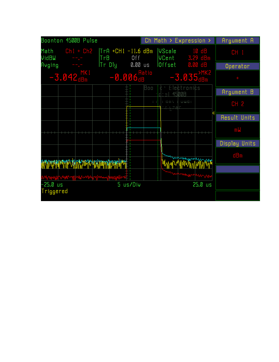
Figure 4-17a. Sum of Channel 1 and Channel 2 power. Markers indicate Math Channel (Ch1 + Ch2) power.

Pages: 1 … 95 96 97 98 99 … 372
  • wrong Brand
  • wrong Model
  • non readable
See also other documents in the category Boonton Measuring instruments:
  • Power Sensor (52 pages)
  • 4540 Peak Power Meter User Manual (270 pages)
  • 4540 Peak Power Meter Quick Start (42 pages)
  • 4530 Peak Power Meter User Manual (170 pages)
  • 4530 Peak Power Meter Service Manual (37 pages)
  • 4240 RF Power Meter (128 pages)
  • 52000 Series USB CW Power Sensor (68 pages)
  • The New 55 Series Wideband USB Power Sensor (28 pages)
  • Sensor Security Procedures (1 page)
  • Wideband Peak Power Sensors (4 pages)
  • 9240 RF Voltmeter (100 pages)
  • 8201A Modulation Analyzer Quick Start (14 pages)
  • PIM 21 User Manual (31 pages)
  • PIM 21 Quick Start (2 pages)
  • PIM 31 Remote Control (5 pages)
  • PIM 31 Quick Start (6 pages)
  • PIM 31 User Manual (110 pages)
Home Brands Popular manuals Recently added
Manuals Directory

© 2012–2025, azmanual.top
All rights reserved.