Boonton 4500b rf peak power analyzer, Operation – Boonton 4500B Peak Power Meter User Manual
Page 96
Boonton 4500B RF Peak Power Analyzer
Operation
4-24
Table 4-4B. Chan # > Extensions > Define Pulse > Submenu (continued)
Menu Item
Function
(Type)
Selections
(SCPI cmd)
HINT
If you want to use 10% and 90% reference levels in measuring risetime, and you want to use the rule of
thumb relationship between risetime and bandwidth, always set Pulse Units to Volts. If you also want to
view a waveform that most closely resembles an oscilloscope display of the same signal, set the display
units to Volts. The display units setting is optional and will not affect the automeasure result.
Start Gate
Pulse
Sets the beginning of the pulse measurement region as a percentage of
(Numeric)
Continuous range:
pulse width
0.00 % to 40.00 %
SENSe[1|2|3|4|6|7]:PULSe:STARTGT <0.00 to 40.00> (percent)
.
End Gate
Pulse
Sets the end of the pulse measurement region as a percentage of pulse
(Numeric)
Continuous range:
width
60.00 % to 100.00 %
SENSe[1|2|3|4|6|7]:PULSe:ENDGT <60.00 to 100.00> (percent)
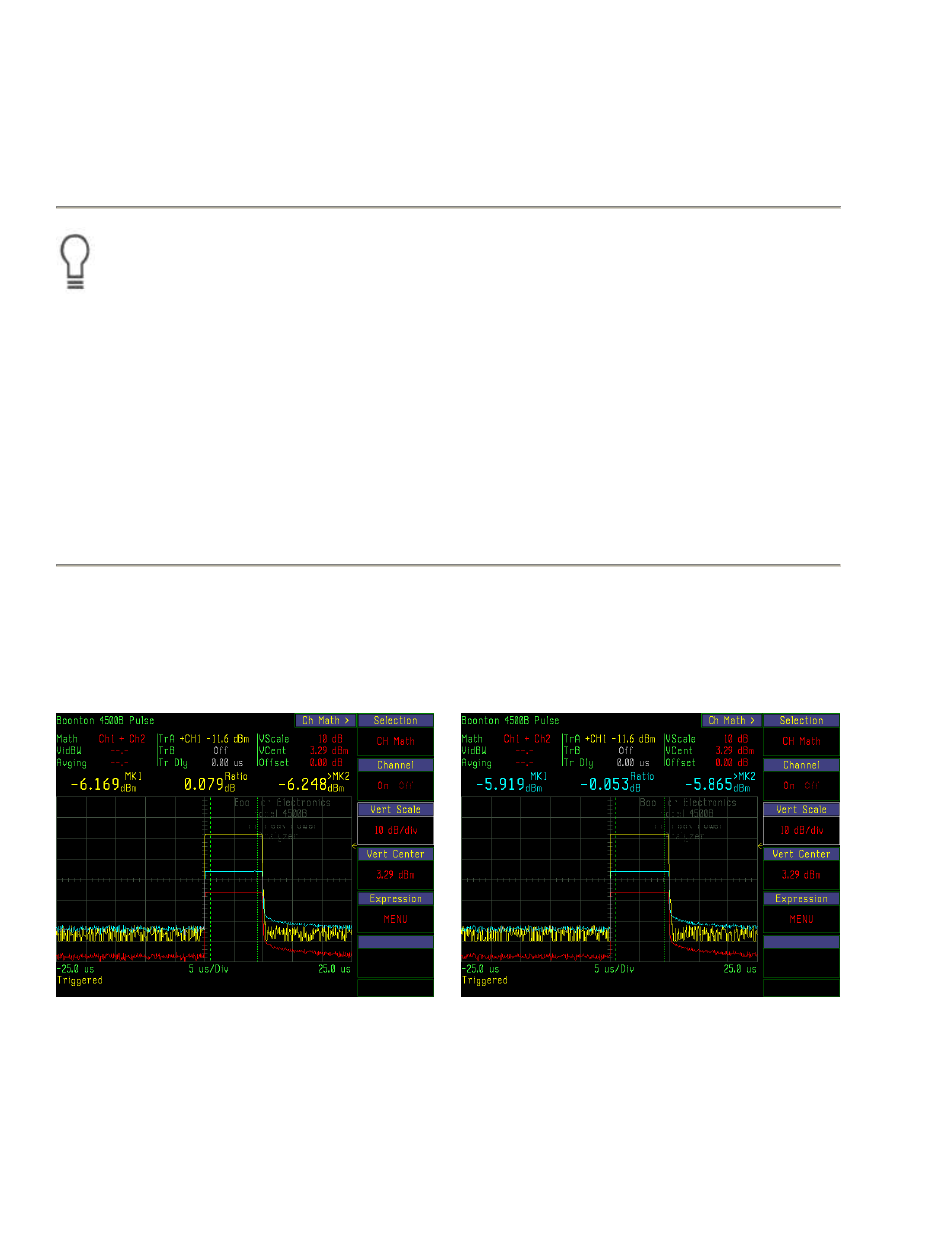
Fig. 4-17b. Markers Indicate Channel 1 power.
Fig. 4-17c. Markers Indicate Channel 2 power.