Boonton 4500b rf peak power analyzer – Boonton 4500B Peak Power Meter User Manual
Page 322
Boonton 4500B RF Peak Power Analyzer
Application Notes
6-12
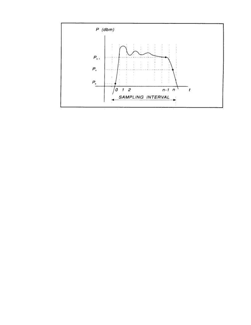
Figure 6-7
Sampling Intervals
14. The processor calculates the delay between the two measurement channels. The
time reference for each channel is established by the first signal crossing
(starting from the left edge of the screen) which passes through the mesial
level(or 50% point in trigger view). The signal excursion must be at least 6 dB
in power mode, or 300 mV in trigger-view mode.