Boonton 4500b rf peak power analyzer, Operation – Boonton 4500B Peak Power Meter User Manual
Page 158
Boonton 4500B RF Peak Power Analyzer
Operation
4-86
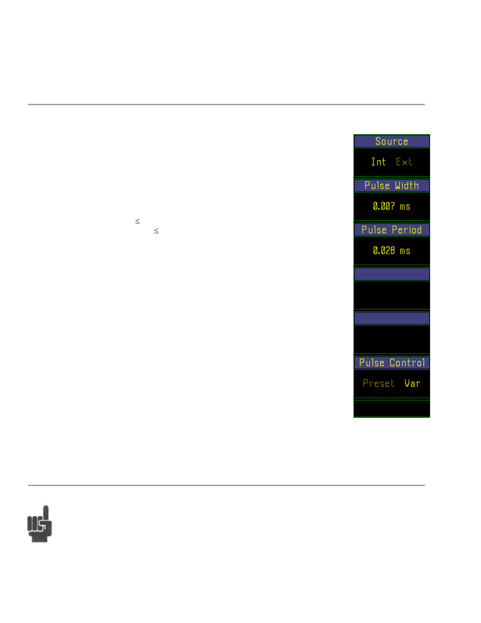
Table 4-33. Calibrator > Pulse (Variable) > Submenu
Menu Item
Function
(Type)
Selections
(SCPI cmd)
Source
Int, Ext
Selects the source for the calibrator output pulse modulation
(Toggle)
Press the Calibrator > Pulse > menu key to
specify whether the calibrator output pulse is
to be internally or externally generated.
OUTPut:PULSe:SOURce {INT, EXT}
Pulse Width
Continuous Range:
Set variable mode pulse width
(Numeric)
7 us to 65.535 ms, for
period 65.542 ms, and Use any of the data entry controls to enter
width + 7us period;
the pulse width.
Min width increases
with increasing period
above period = 65.544
ms.
See below: OUTPut:PULSe:PERWID
Pulse Period
Continuous Range:
Set variable mode pulse period
(Numeric)
28 us to 131.077 ms;
Pulse width must be
Use any of the data entry controls to enter the
compatible.
the pulse period.
OUTPut:PULSe:PERWID
Pulse Control
Preset, Var
Selects the Preset or Variable internal Pulse
(Toggle)
modulator
Press the Calibrator > Pulse > Pulse Control Fig. 4-47. Calibrator
menu key to select the Preset method of
> Pulse > (Variable
internal pulse modulation control.
See Table 4-31.
OUTPut:PULSe:CTRL {PRESET, VAR}
NOTE
Calibrator pulse modulation can also be supplied by an external pulse generator via the rear-mounted BNC
connector labeled ―EXT PULSE‖. Select ―Ext‖ in the Calibrator > Pulse > Source menu window. TTL-
level signals connected at this input port will gate the 1 GHz calibration signal on and off. A low level
signal turns the RF output off.