Boonton 4500b rf peak power analyzer, Operation – Boonton 4500B Peak Power Meter User Manual
Page 127
Boonton 4500B RF Peak Power Analyzer
Operation
4-55
Table 4-12. Mark > Extensions > Submenu (continued)
Menu Item
Function
(Type)
Selections
(SCPI cmd)
Each marker can be assigned to the memory channels also. All marker
functions will function on the memory channels including minimum
and maximum power measurements between markers and average
power between markers.
MARKer[1/2]:ASSIgn {ACTIVE, CH1, CH2, TRIG1, TRIG2,
CHM, MEM1, MEM2}
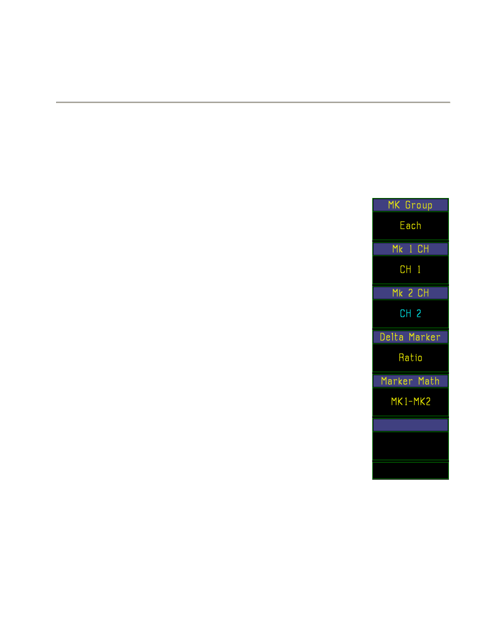
Delta Marker
Pulse & Mod
Selects the function of the center marker
(Mult. Choice)
Ratio, Avg,
window above the graphical display
Delta
Use Mark > Marker # menu function to place
the time markers in the active window at
the points of interest on the waveform. Press
the Mark > Delta Marker menu key to select
either ―Ratio‖, ―Avg.‖ , or "Delta". (―Delta‖
is available for non-logarithmic units only.)
Select ―Ratio‖ to display the power (or
voltage) ratio of Marker 1 and Marker 2 in
the center window. If Marker 1 and Marker 2
are expressed in logarithmic units, ratio will
be in dB. If Marker 1 and Marker 2 are
expressed in linear (non-logarithmic) units,
the ratio will be in percent.
Select ―Avg‖ to display the average power
(or voltage) in the waveform interval between
the two markers. The average power (or
voltage) will be expressed in the same units
as the Markers 1 and 2.
The ―Avg‖ selection is available only when
Mark > Extensions > Mk Group Both is
selected. When Mark > Extensions >
Mk Group Each is selected, the Delta Marker
selection is automatically switched to
―Ratio.‖ When Mark > Extensions > Mk
Group Both is reselected, the Delta Marker
selection returns to ―Avg.‖
Fig. 29b
The "Delta" selection is available only for Mark > Exten menu
linear (non-logarithmic) units (e.g. watts,
Each – CH1,Ch2
volts). The delta function displays the
power (or voltage) difference between