Boonton 4500b rf peak power analyzer, Getting started – Boonton 4500B Peak Power Meter User Manual
Page 42
Boonton 4500B RF Peak Power Analyzer
Getting Started
3-8
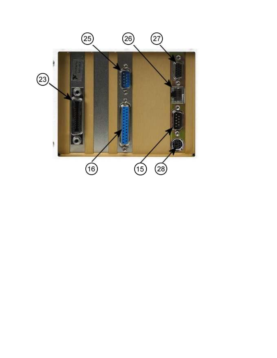
Figure 3-2a. Model 4500B - Rear Panel I/O connectors
Table 3-1 Operating Controls, Indicators and Connections
(continued)
Ref. No.
Front Rear Nomenclature
Function
15
COM1 RS-232C Connector
16
LPT1 Parallel Printer Connector (Centronics)
17
Fuse holder (See Table 1-1).
18
Intake cooling fan and filter
19
Exhaust cooling fan
20
NEMA power cord connector. Supplies AC power to the instrument (see
Subsection 2.2).
21
Power switch. Connects or disconnects all power to the instrument; overrides
PWR switch.