IAI America XSEL-QX User Manual
Page 477
453
Appendix
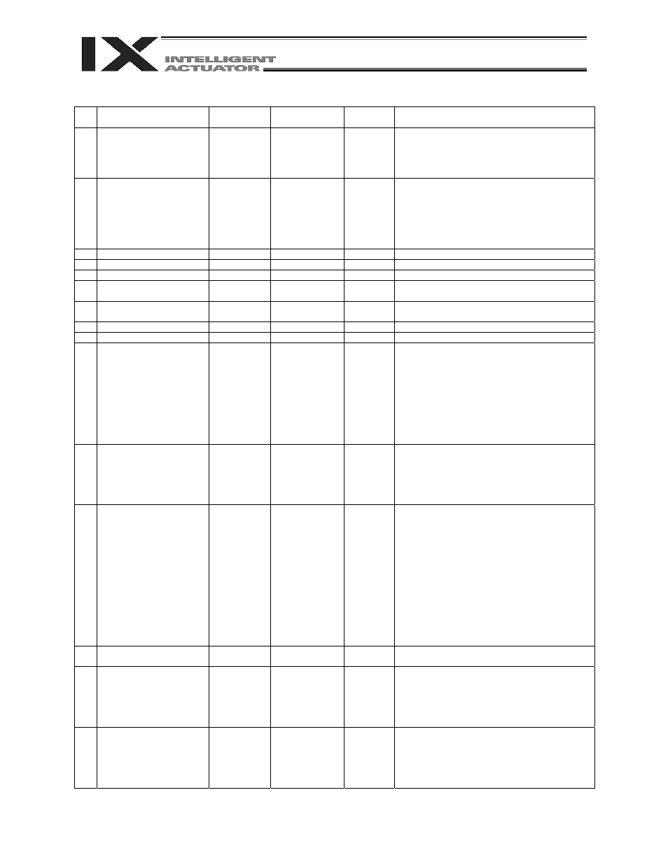
Axis-Specific Parameters
No. Parameter
name
Default value
(Reference)
Input range
Unit
Remarks
67 Short-cut
control
selection
for rotational movement
axis (linear movement
axis)
0
0 ~ 5
Reference only
for SCARA axes
(axes 1 to 4)
0: Do not select, 1: Select (Valid only in the index
mode AND when an incremental encoder is used)
* Valid for linear movement axes (axes 5 and 6
(6-axis type)) only.
(Main application version 0.12 or later)
68 Mode selection for linear
movement axis (linear
movement axis)
0
0 ~ 5
Reference only
for SCARA axes
(axes 1 to 4)
0: Normal, 1: Infinite-stroke mode (Note:
Positioning boundary applies. This parameter can
be specified only when an incremental encoder is
used.)
* Valid for linear movement axes (axes 5 and 6
(6-axis type)) only.
(Main application version 0.12 or later)
69 (For
extension)
0
~
70 For future extension
0
Reference only
For adjustment by the manufacturer
71 For future extension
0
Reference only
For adjustment by the manufacturer
72 For future extension
(Change prohibited)
0
Reference only
DRVVR
For adjustment by the manufacturer
73 For future extension
(Change prohibited)
0
Reference only
DRVVR
For adjustment by the manufacturer
74 For future extension
0
Reference only
For adjustment by the manufacturer
75 For future extension
0
Reference only
For adjustment by the manufacturer
76 For future extension
(Change prohibited)
0 0H
~
FFFFFFFFH
(Change
prohibited)
0: P21 = Phase-Z evacuation distance at
incremental home return
P12 = Ideal phase-Z position coordinate
1: Automatically acquire P32 even when P33 = 0.
P33 = 0 “= Actual distance”
P21 = Offset travel distance at home return
P12 = Coordinate after offset travel at home
return
P26 is invalid (to make adjustment easy).
77 Synchro S pulse of linear
movement axis
0,
0,
0,
0,
3,
3
0 ~ 99999
Reference only
for SCARA axes
(axes 1 to 4)
Pulse
* Valid for linear movement axes (axes 5 and 6
(6-axis type)) only.
(Main application version 0.12 or later)
78 Maximum
takeoff
command amount
0
-3000 ~ 3000
0.001 mm
Maximum lift command amount before brake
unlock (Input with sign)
(Suppression of momentary drop upon servo ON
when a heavy object is placed)
* Important: Input using the same sign as the
rising coordinate direction. (0.100
mm to 0.500 mm in absolute value
as a guideline)
* The servo-ON check time (axis-specific
parameter No. 30) must also be extended
(approx. 1000 to 1500 msec) to provide a
sufficient time for rise-direction torque to
follow. (This setting is valid only when a brake
is equipped.)
79 Actual takeoff check
distance
5
0 ~ 3000
0.001 mm
Absolute value input
80 Maximum
forced-feed
range of linear movement
axis
0
0 ~ 9999
Reference only
for SCARA axes
(axes 1 to 4)
0.001 mm
For reduction of settling time.
(Invalid range if “0” is set)
(Approx. 1.000 mm as a guideline)
* Valid for linear movement axes (axes 5 and 6
(6-axis type)) only.
(Main application version 0.12 or later)
81 Minimum
forced-feed
range of linear movement
axis
0,
0,
0,
0,
200,
200
0 ~ 9999
Reference only
for SCARA axes
(axes 1 to 4)
0.001 mm
* Valid for linear movement axes (axes 5 and 6
(6-axis type)) only.
(Main application version 0.12 or later)