External interrupt control – Toshiba H1 Series User Manual
Page 85
TMP92CZ26A
92CZ26A-82
(2)
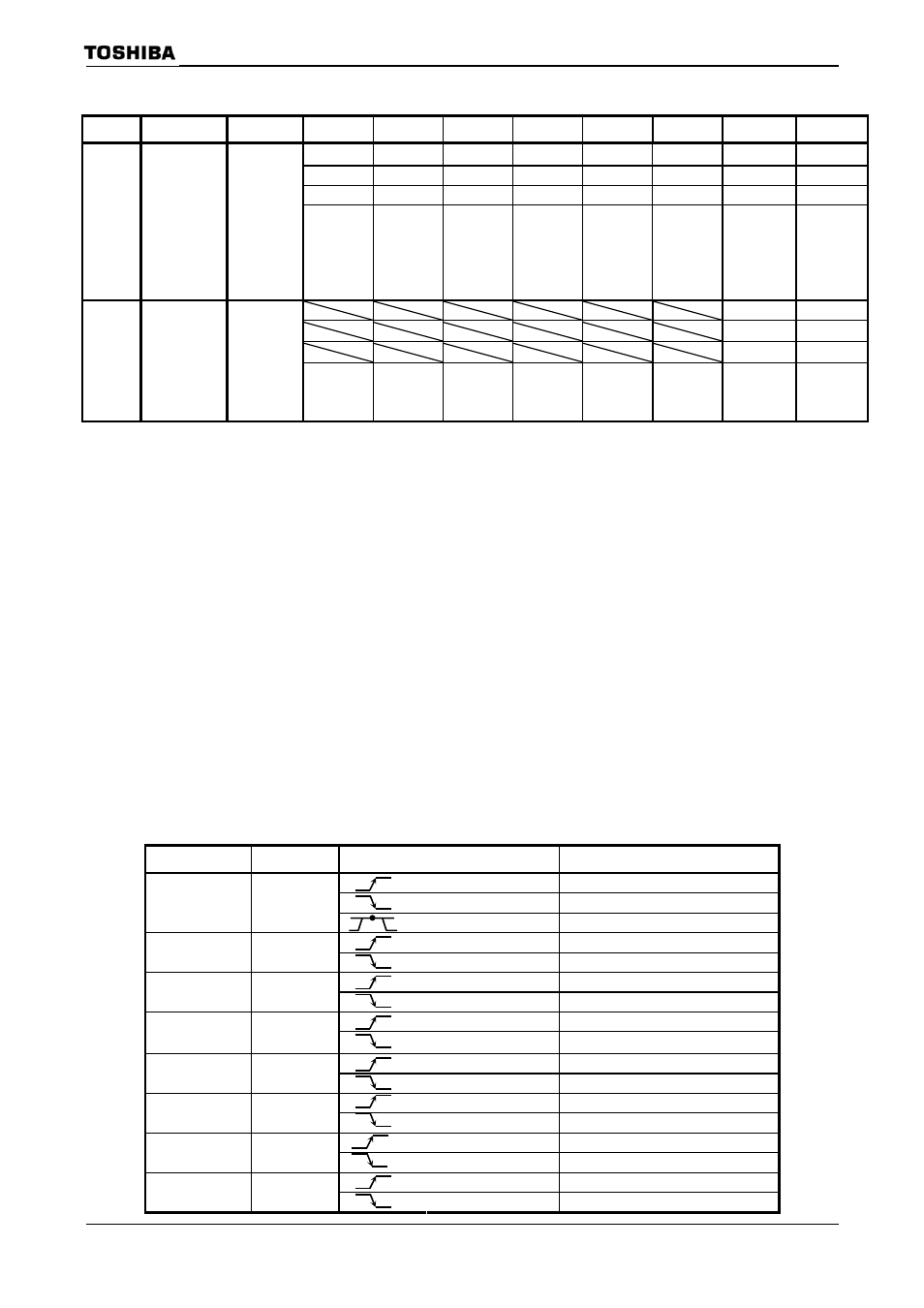
External interrupt control
Symbol
Name
Address
7 6 5 4 3 2 1 0
I5EDGE I4EDGE
I3EDGE
I2EDGE
I1EDGE
I0EDGE
I0LE
−
W W W W W W R/W
R/W
0 0 0 0 0 0 0 0
IIMC0
Interrupt
input mode
control 0
F6H
(Prohibit
RMW)
INT5EDGE
0: Rising
1: Falling
INT4EDGE
0: Rising
1: Falling
INT3EDGE
0: Rising
1: Falling
INT2EDGE
0: Rising
1: Falling
INT1EDGE
0: Rising
1: Falling
INT0EDGE
0: Rising
1: Falling
INT0
0: Edge
mode
1: Level
mode
Always
write “0”
.
I7EDGE
I6EDGE
W W
0 0
IIMC1
Interrupt
input mode
control 0
FAH
(Prohibit
RMW)
INT7EDGE
0: Rising
1: Falling
INT6EDGE
0: Rising
1: Falling
Note 1: Disable INT0 request before changing INT0 pin mode from level sense to edge sense.
(change
DI
LD
(IIMC0), XXXXXX0-B
; Switches from level to edge.
LD
(INTCLR), 0AH
; Clears interrupt request flag.
NOP
;
Wait
EI
execution
NOP
NOP
EI
Note 2: X: Don’t care, –: No change
Note 3: See electrical characteristics in section 4 for external interrupt input pulse width.
Note 4: In port setting, if 16 bit timer input is selected and capture control is executed, INT6 and
INT7 don’t depend on IIMC1 register setting. INT6 and INT7 operate by setting
TBnMOD
Settings of External Interrupt Pin Function
Interrupt
Pin Name
Mode
Setting Method
Rising edge
Falling edge
INT0 PC0
High level
Rising edge
INT1 PC1
Falling edge
Rising edge
INT2 PC2
Falling edge
Rising edge
INT3 PC3
Falling edge
Rising edge
INT4 P96
Falling edge
Rising edge
INT5 PP3
Falling edge
Rising edge
INT6 PP4
Falling edge
Rising edge
INT7 PP5
Falling edge