1 system configuration – Toshiba H1 Series User Manual
Page 370
TMP92CZ26A
92CZ26A-367
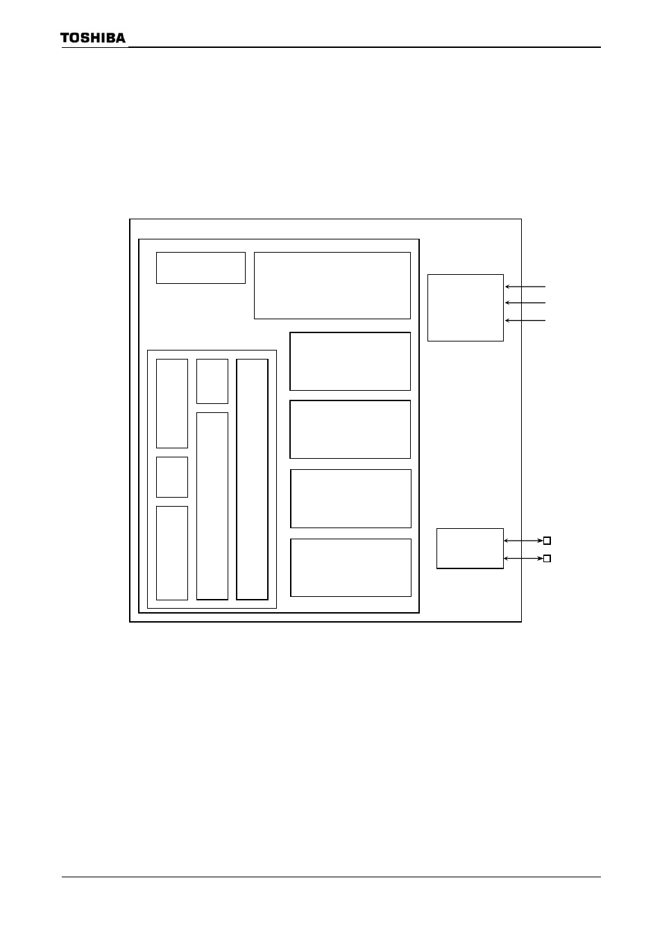
3.16.1.1 System Configuration
The USB controller (UDC) is consisted of following 3 blocks.
1. 900/H1
CPU
I/F
2. UDC core block (DPLL, SIE, IFM and PWM), request controller, descriptor RAM
and 4 endpoint FIFO
3. USB
transceiver
About above “1.” is explained at 3.16.2, and “2.” is 3.16.3.
Figure 3.16.1 UDC Block Diagram
Descriptor RAM
384 bytes
Request controller
Endpoint 0:
FIFO (64 bytes
× 1)
Endpoint 1:
FIFO (64 bytes
× 2)
Endpoint 2:
FIFO (64 bytes
× 2)
Endpoint 3:
FIFO (8 bytes
× 1)
PWM
DPLL
SIE
IFM
I/F
FIFO
manager
900/H1 CPU
interface
USB
transceiver
UDC core
ADDRESS
RD
WR
D
+
UDC
D
−
This manual is related to the following products: