Toshiba H1 Series User Manual
Page 524
TMP92CZ26A
92CZ26A-521
Example 1: When f
SYS
= 10 MHz, STN mode, LCDMODE0
Internal reference clock LCP0 = f
SYS
/ 8 = 10 MHz / 8 = 1.25 [MHz]
LCP0 period = 1 / 1.25 [MHz] = 0.8 [
μS]
Example 2: when f
SYS
= 60 MHz, TFT mode, LCDMODE0
Internal reference clock LCP0 = f
SYS
/ 16 = 60 MHz / 16 = 3.75 [MHz]
LCP0 period = 1 / 3.75 [MHz] = 266 [nS]
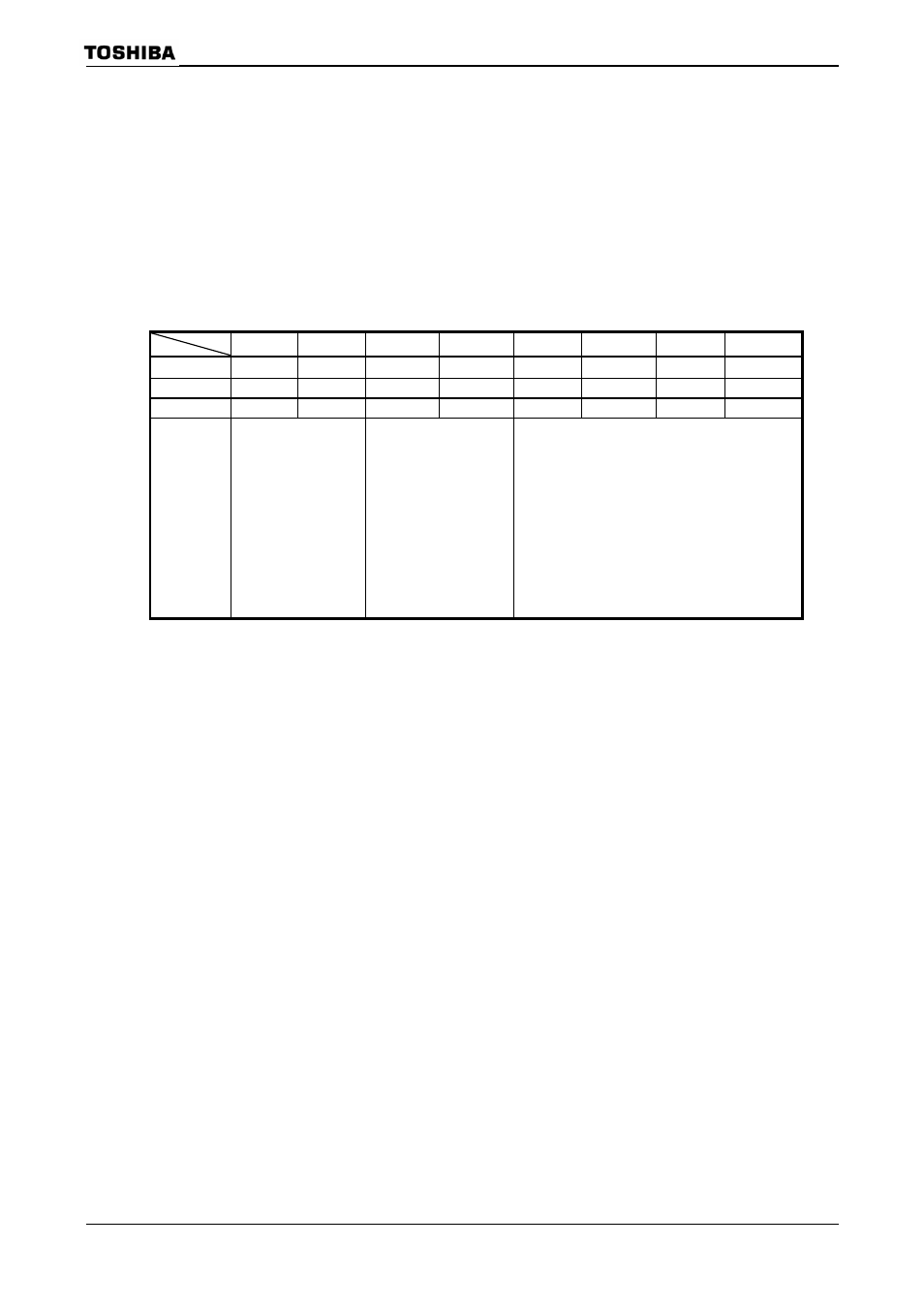
LCDMODE0 Register
7 6 5 4 3 2 1 0
bit Symbol
RAMTYPE1 RAMTYPE0
SCPW1 SCPW0 MODE3
MODE2 MODE1 MODE0
Read/Write
R/W R/W R/W R/W R/W R/W R/W R/W
After
reset
0 0 1 1 0 0 0 0
Function
Display RAM
00: Internal RAM
(32-bit)
01: External SRAM
10: SDRAM
11: Reserved
LD bus transfer speed
SCPW2= 0
00:
2-clk
01:
4-clk
10:
8-clk
11:
16-clk
SCPW2= 1
00:
6-clk
01:
12-clk
10:
24-clk
11:
48-clk
Mode selection
0000: Reserved
1000: Reserved
0001: SR (mono)
1001: Reserved
0010: SR (4-gray)
1010: TFT (256-color)
0011: Reserved
1011: TFT (4096-color)
0100: SR (16-gray)
1100: TFT (64K-color)
0101: SR (64-gray) 1101: TFT(256K-,16M-color)
0110: STN (256-color) 1110: Reserved
0111: STN (4096-color) 1111: Reserved
LCDMODE0
(0280H)