Figure 3.23.6 ad conversion registers – Toshiba H1 Series User Manual
Page 603
TMP92CZ26A
92CZ26A-600
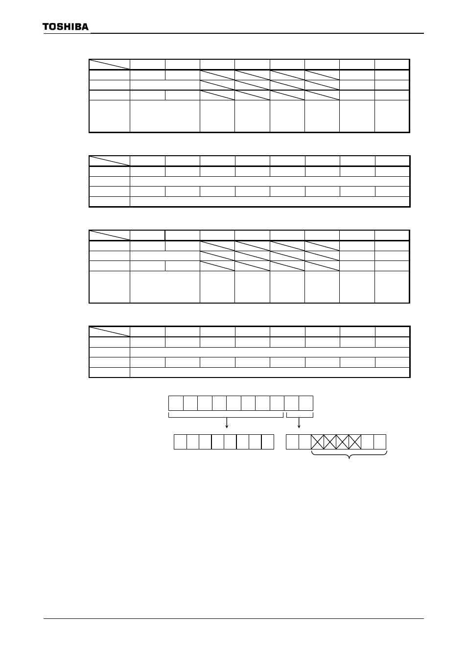
AD Conversion Result Register 0 Low
7 6 5 4 3 2 1 0
bit
Symbol
ADR01
ADR00
OVR0
ADR0RF
Read/Write R
R
R
After
reset
0
0 0
0
Function
Store Lower 2 bits of
AN0 AD conversion
result
Overrun flag
0:No generate
1: Generate
AD conversion
result store
flag
1: Stored
AD Conversion Result Register 0 High
7 6 5 4 3 2 1 0
bit Symbol
ADR09
ADR08
ADR07
ADR06 ADR05 ADR04 ADR03 ADR02
Read/Write R
After
reset
0 0 0 0 0 0 0 0
Function
Store Upper 8 bits of AN0 AD conversion result
AD Conversion Result Register 1 Low
7 6 5 4 3 2 1 0
bit
Symbol
ADR11
ADR10
OVR1
ADR1RF
Read/Write R
R
R
After
reset
0
0 0
0
Function
Store Lower 2 bits of
AN1 AD conversion
result
Overrun
flag
0:No generate
1: Generate
AD conversion
result store
flag
1: Stored
AD Conversion Result Register 1 High
7 6 5 4 3 2 1 0
bit Symbol
ADR19
ADR18
ADR17
ADR16 ADR15 ADR14 ADR13 ADR12
Read/Write R
After
reset
0 0 0 0 0 0 0 0
Function
Store Upper 8 bits of AN1 AD conversion result
9
8
7
6
5
4
3
2
1
0
Channel X conversion result
7 6
5
4
3
2
1
0
7
6
5
4 3 2 1 0
Figure 3.23.6 AD Conversion Registers
ADREG0L
(12A0H)
ADREG0H
(12A1H)
ADREG1H
(12A3H)
ADREGxH ADREGxL
• Bits
5
∼ 2 are always read as “0”.
•
Bit 0 is the AD conversion result store flag
When Lower register (ADRECxL) is read, this bit is cleared to “0”.
•
Bit 1 is the Overrun flag
before both the ADREGxH and ADREGxL are read. This bit is cleared to “0” by reading Flag.
ADREG1L
(12A2H)