X: don't care, −: no change – Toshiba H1 Series User Manual
Page 313
TMP92CZ26A
92CZ26A-310
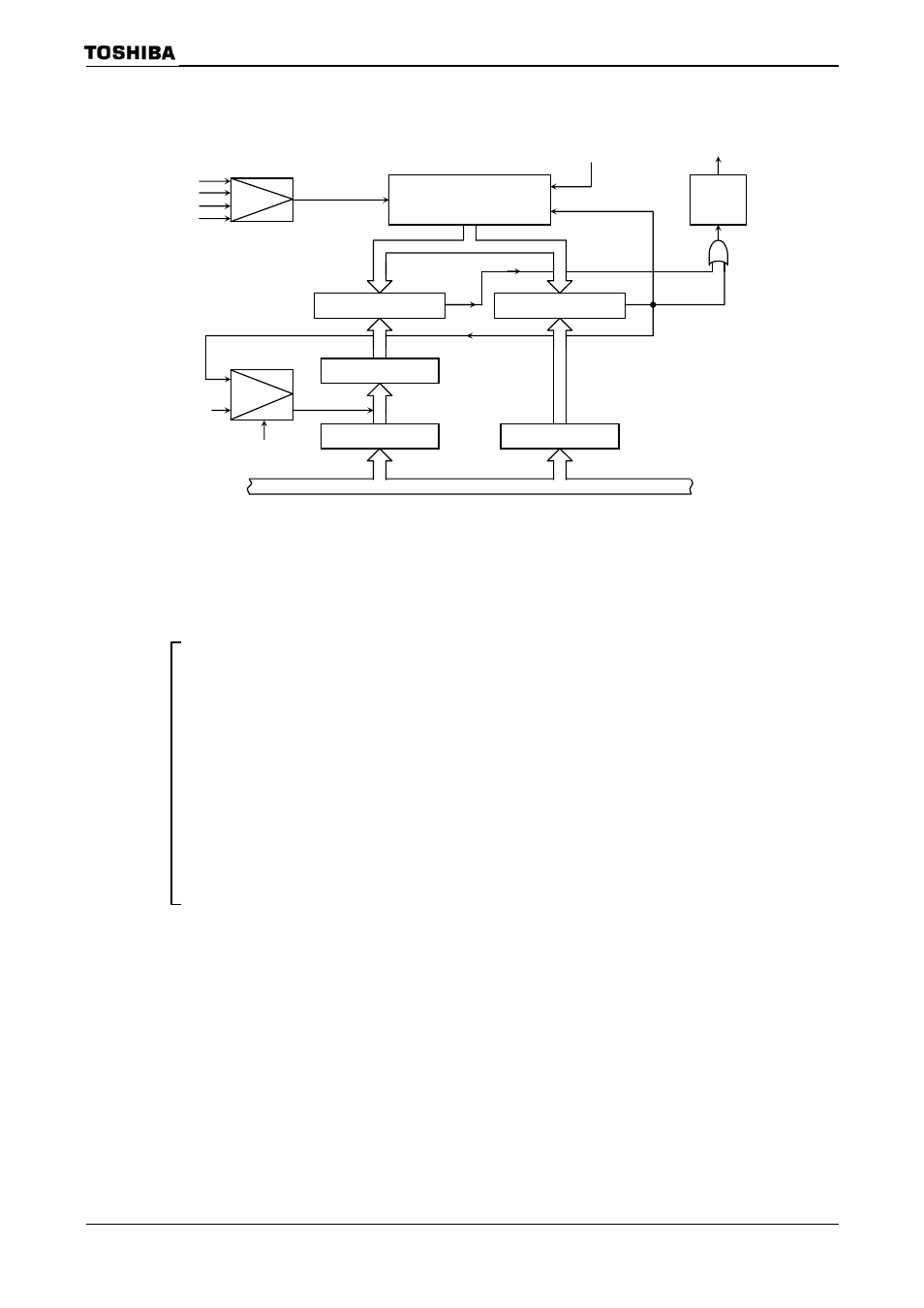
The following block diagram illustrates this mode.
Figure 3.13.11 Block Diagram of 16-Bit Mode
The following example shows how to set 16-bit PPG output mode:
7
6
5
4
3
2
1
0
TB0RUN
← 0 0 X X –
–
X
0
Disable the TB0RG0 double buffer and stop TMRB0.
TB0RG0
← *
*
*
*
*
*
*
*
Set the duty ratio
*
*
*
*
*
*
*
*
(16 bit)
TB0RG1
← *
*
*
*
*
*
*
*
Set the frequency
*
*
*
*
*
*
*
*
(16 bit)
TB0RUN
← 1 0 X X –
0
X
0
Enable the TB0RG0H/L double buffer.
(The duty and frequency are changed on an INTTB01
interrupt.)
TB0FFCR
← X X
0
0
1
1
1
0
Set the mode to invert TB0FF0 at the match with
TB0RG0H/L/TB0RG1H/L. Set TB0FF0 to 0.
TB0MOD
← 0 0 1 0 0
1
*
*
Select the internal clock as the input clock and disable
(**
= 01, 10, 11)
the capture function.
PPFC
← – 1 – – –
–
–
X
Set PP6 to function as TB0OUT0
TB0RUN
← 1 0 X X –
1
X
1
Start
TMRB0.
X: Don't care,
−: No change
Selector
16-bit up counter
UC10
16-bit comparator
16-bit comparator
TB0IN0
φT1
φT4
φT16
F/F
(TB0FF0)
TB0RG0H/L
Register buffer 0
TB0RG1H/L
TB0RUN
TB0RG0-WR
TB0RUN
TB0OUT0 (PPG output)
Internal data bus
Clear
Match
Selector