Toshiba H1 Series User Manual
Page 495
TMP92CZ26A
92CZ26A-492
(4) SPICR (SPI CRC Register)
CRC result of Transmit/Receive data is set to SPICR register.
SPICR Register
7 6 5 4 3 2 1 0
bit Symbol
CRCD7 CRCD6 CRCD5
CRCD4
CRCD3
CRCD2
CRCD1 CRCD0
Read/Write
R
After Reset
0 0 0 0 0 0 0 0
Function
CRC result register [7:0]
15 14 13 12 11 10 9 8
bit Symbol
CRCD15
CRCD14
CRCD13
CRCD12
CRCD11
CRCD10
CRCD9 CRCD8
Read/Write
R
After Reset
0 0 0 0 0 0 0 0
Function
CRC result register [15:8]
Figure 3.17.11 SPICR Register
(a)
The result which is calculated according to the setting; SPICT
In case CRC16, all bits are valid.
In case CRC7, lower 7 bits are valid.
The flow will be showed to calculate CRC16 of received data for instance by flowchart.
Firstly, initialize CRC calculation register by writing
setting
Next, finish transmitting all bits to calculate CRC by writing data in SPITD register.
Please sense SPIST
If read SPICR register after finishing, CRC16 of received data can be read.
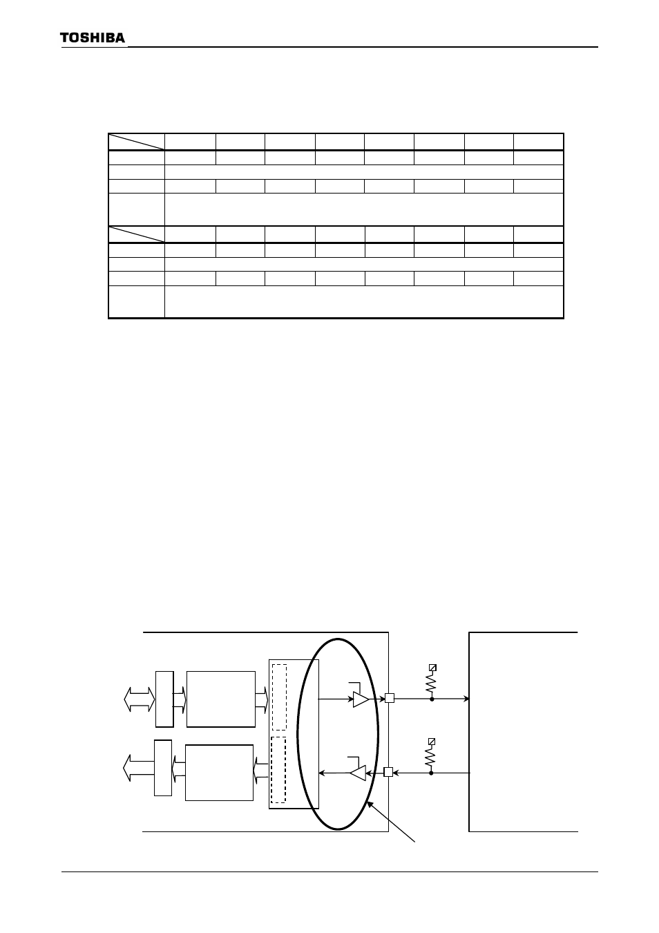
Note: CRC is generated in I/O point. Please take care soft ware process to compare the CRC when
used FIFO.
SPICR
(826H)
(827H)
SPITD
T
rans
mitt,Rec
eiv
e
ont
roller
SPDO
16bit
SPIRD
SPDI
DI
DO
100K
Ω
100K
Ω
Internal dat
a b
u
s
TX FIFO
8
×32
RX FIFO
8
×32
16bit
RX shift re
gister
TX shft r
egi
ster
TMP92CZ26A
SPI slave
CRC generation point