5 noise reduction circuits – Toshiba H1 Series User Manual
Page 34
TMP92CZ26A
92CZ26A-31
3.3.5 Noise reduction circuits
Noise reduction circuits are built in, allowing implementation of the following features.
(1) Reduced drivability for high-frequency oscillator circuit
(2) Reduced drivability for low-frequency oscillator circuit
(3) Single drive for high-frequency oscillator circuit
(4) SFR protection of register contents
These are set in EMCCR0 to EMCCR2 registers.
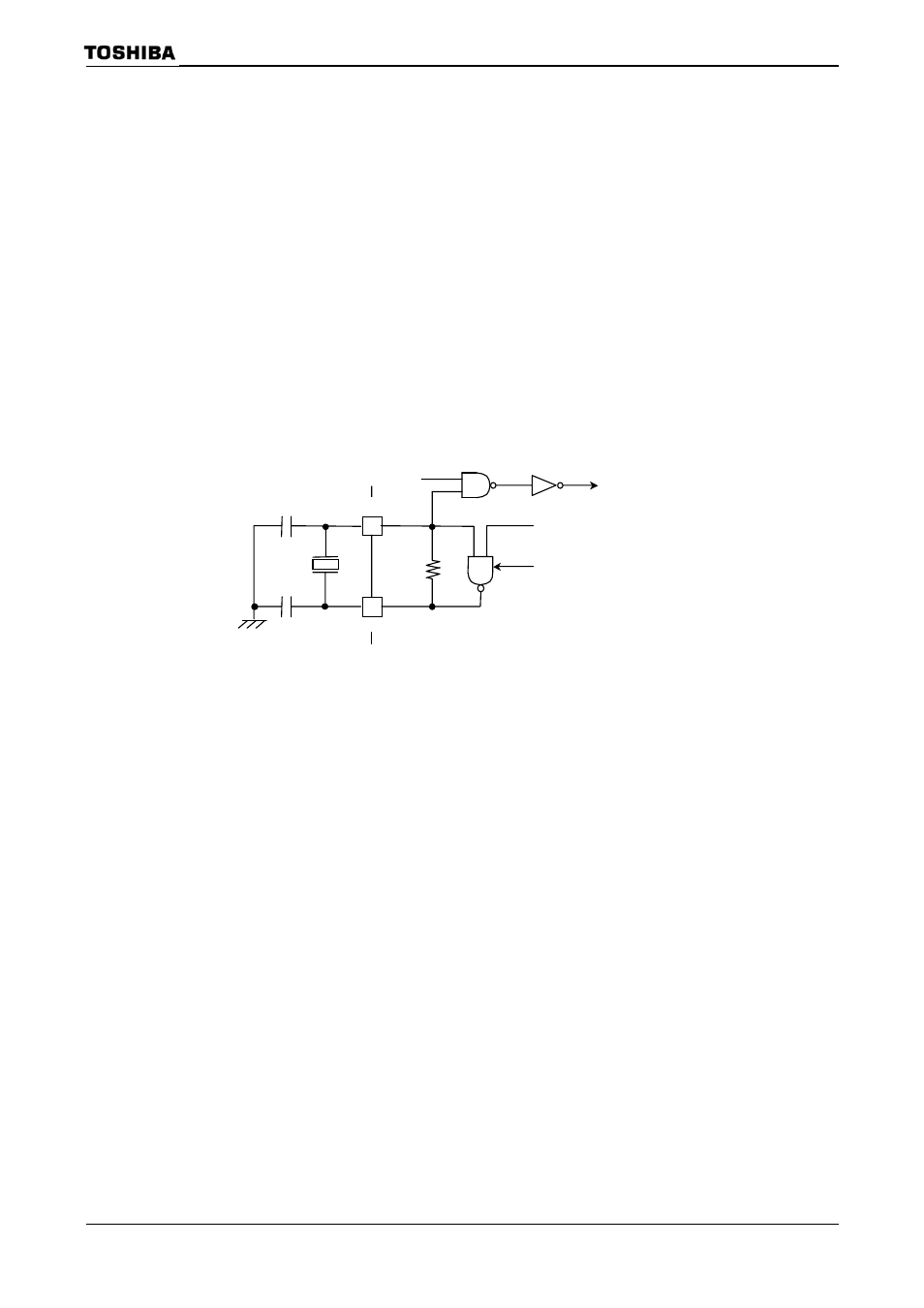
(1) Reduced drivability for high-frequency oscillator circuit
(Purpose)
Reduces noise and power for oscillator when a resonator is used.
(Clock diagram)
resonator
C2
C1
Enable oscillation
X1 pin
EMCCR0
f
OSCH
X2 pin
(Setting method)
The drivability of the oscillator is reduced by writing”0” to EMCCR0
register. By reset,
by normal-drivability when the power-supply is on.
Note: This function (EMCCR0
OSCH
= 6 to 10MHz condition.