Toshiba H1 Series User Manual
Page 323
TMP92CZ26A
92CZ26A-320
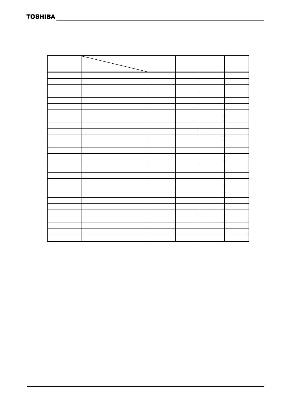
Table 3.14.2 Transfer Rate Selection
(When baud rate generator is used and BR0CR
= 0)
f
SYS
[MHz]
Input Clock
Frequency Divider N
φT0
(f
SYS
/4)
φT2
( f
SYS
/16)
φT8
(f
SYS
/64)
φT32
(f
SYS
/256)
7.3728 1
115.200
28.800
7.200
1.800
3 38.400
9.600
2.400
0.600
6 19.200
4.800
1.200
0.300
A 11.520
2.880
0.720
0.180
C 9.600
2.400
0.600
0.150
F 7.680
1.920
0.480
0.120
9.8304 1
153.600
38.400
9.600
2.400
2 76.800
19.200
4.800
1.200
4 38.400
9.600
2.400
0.600
5 30.720
7.680
1.920
0.480
8 19.200
4.800
1.200
0.300
0 9.600
2.400
0.600
0.150
44.2368 6
115.20
28.800
7.200
1.800
9 76.800
19.200
4.800
1.200
58.9824 2
460.800
115.200
28.800
7.200
3 307.200
76.800
19.200
4.800
5 184.320
46.080
11.520
2.880
6 153.600
38.400
9.600
2.400
8 115.200
28.800
7.200
1.800
C 76.800
19.200
4.800
1.200
F 61.440
15.360
3.840
0.960
73.728 1
1152.000
288.000
72.000
18.000
↑
3 384.000
96.000
24.000
6.000
↑
6 192.000
48.000
12.000
3.000
↑
A 115.200
28.800
7.200
1.800
↑
C 96.000
24.000
6.000
1.500
↑
F 76.800
19.200
4.800
1.200
Note: Transfer rates in I/O interface mode are eight times faster than the values given above.
Timer out clock (TA0TRG) can be used for source clock of UART mode only.
Calculation method the frequency of TA0TRG
Frequency of TA0TRG
= Baud
rate
× 16
Note: In case of I/O interface mode, prohibit to use TA0TRG for source clock.
Unit (kbps)