5 refresh rate – Toshiba H1 Series User Manual
Page 526
TMP92CZ26A
92CZ26A-523
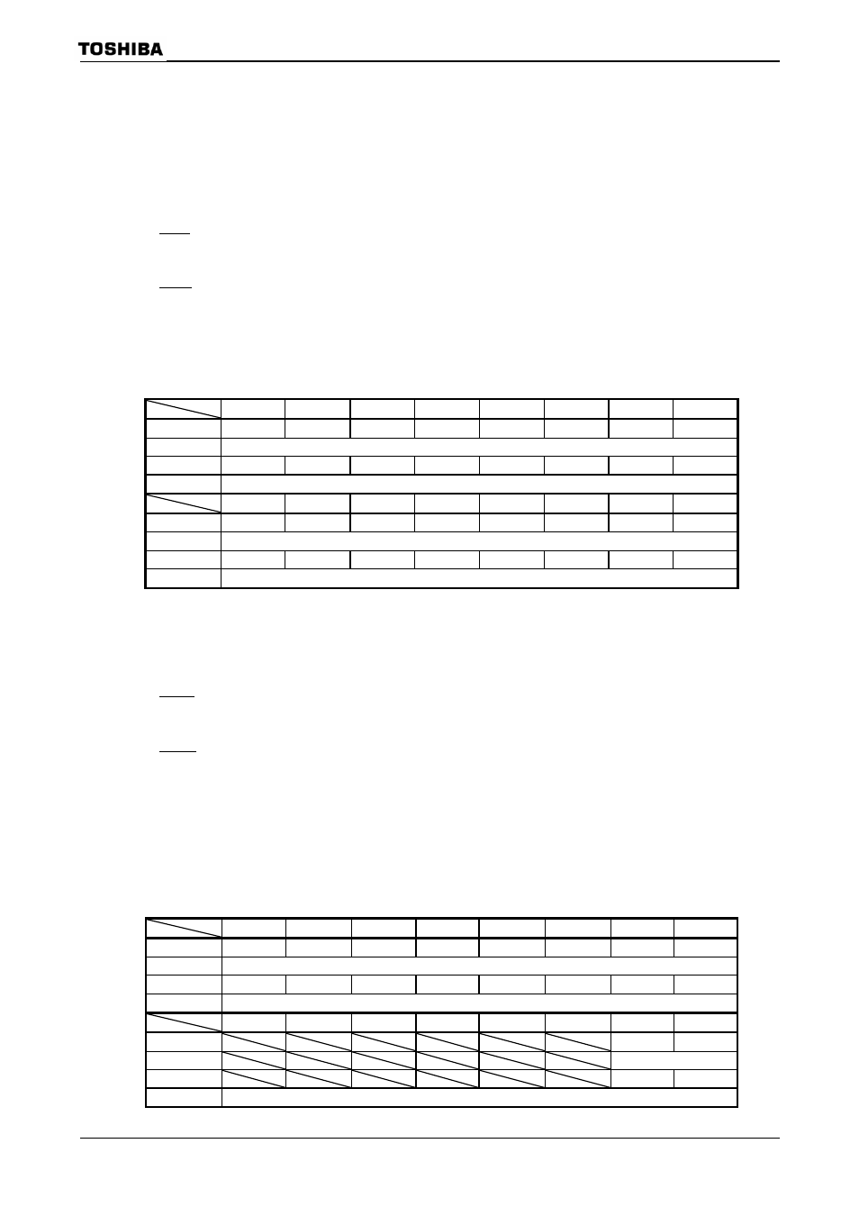
3.19.3.5 Refresh
Rate
The period of the horizontal synchronization signal LHSYNC is defined as the
product of the value set in LCDHSP
The value to be set in LCDHSP
TFT
Segment size + number of dummy clocks
(*)
STN
Monochrome/grayscale : (Segment size / 8)
+ number of dummy clocks
(*)
Color
: (Segment size
× 3 / 8) + number of dummy clocks
(*)
LHSYNC [s: period] = LCP0 [s: period]
× (
LCD LHSYNC Pulse Register
7 6 5 4 3 2 1 0
bit
Symbol
LH7 LH6 LH5 LH4 LH3 LH2 LH1 LH0
Read/Write W
After
reset
0 0 0 0 0 0 0 0
Function
LHSYNC period (bits 7–0)
7 6 5 4 3 2 1 0
bit
Symbol
LH15 LH14 LH13 LH12 LH11 LH10 LH9 LH8
Read/Write W
After
reset
0 0 0 0 0 0 0 0
Function
LHSYNC period (bits 15-8)
The period of the vertical synchronization signal LVSYNC is defined as the product of
the value set in LCDVSP
The value to be set in LCDVSP
TFT
Common size + number of dummy clocks
(*)
STN
Common size
+ number of dummy clocks
(*)
(A minimum of one dummy clock must be inserted in the back
porch.)
LVSYNC [s: period] = LHSYNC [s: period]
× (
= LCP0 [s: period] × (
+ 1) × (
LCD V SYNC Pulse Register
7 6 5 4 3 2 1 0
bit
Symbol
LVP7 LVP6 LVP5 LVP4 LVP3 LVP2 LVP1 LVP0
Read/Write W
After
reset
0 0 0 0 0 0 0 0
Function
LVSYNC period (bits 7-0)
7 6 5 4 3 2 1 0
bit
Symbol
LVP9
LVP8
Read/Write
W
After
reset
0
0
Function
LVSYNC period (bits 9-8)
LCDHSP
(028AH)
(028BH)
LCDVSP
(028CH)
(028DH)