Toshiba H1 Series User Manual
Page 340
TMP92CZ26A
92CZ26A-337
Main routine
7
6
5
4
3
2
1
0
P9CR
← X X X X X −
0
−
Set P91 to function as the RXD0 pin.
P9FC
← − −
X
X
X
−
X
−
SC0MOD0
← − −
1
−
1
0
0
1
Enable receiving in 8-bit UART mode.
SC0CR
← − 0
1
−
−
−
−
−
Add odd parity.
BR0CR
← 0 0
0
1
1
0
0
0
Set the transfer rate to 9600 bps.
INTES0
← X 1
0
0
X
0
0
0
Enable the INTTX0 interrupt and set it to interrupt
level 4.
Interrupt routine
A
CC
← SC0CR AND 00011100
if A
CC
≠ 0 then ERROR
Check for errors
A
CC
← SC0BUF
Read the received data
X: Don't care,
−: No change
(4) Mode 3 (9-Bit UART Mode)
9-Bit UART Mode is selected by setting SC0MOD0
parity bit cannot be added.
In the case of transmission the MSB (9th bit) is written to SC0MOD0
case of receiving it is stored in SC0CR
MSB is read or written first, before the rest of the SC0BUF data.
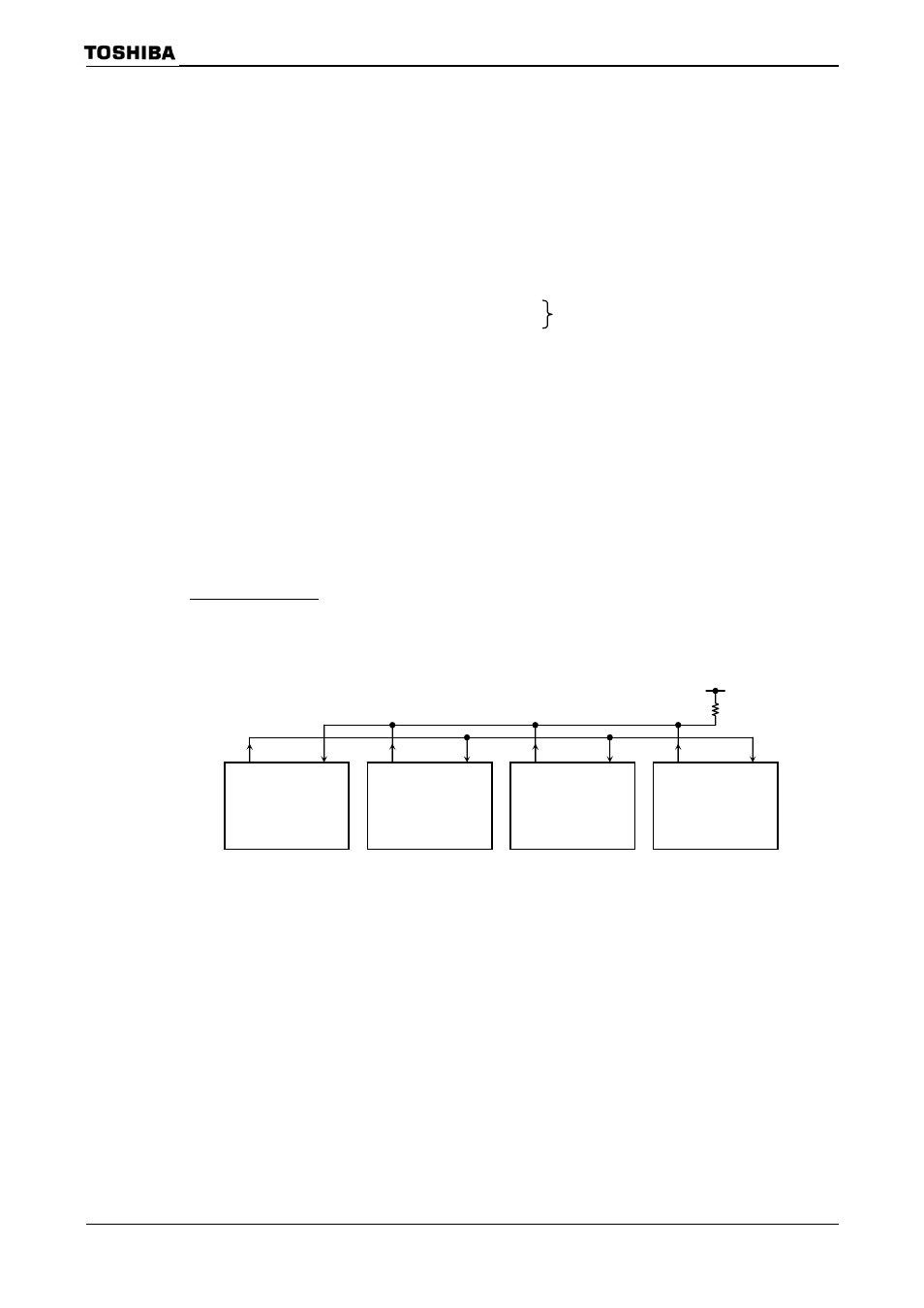
Wake-up function
In 9-Bit UART Mode, the wake-up function for slave controllers is enabled by
setting SC0MOD0
when
Note: The TXD pin of each slave controller must be in Open-Drain Output Mode.
Figure 3.14.17 Serial Link using Wake-up function
TXD
RXD
Master
TXD
RXD
Slave1
TXD
RXD
Slave 2
TXD
RXD
Slave 3