4 description of registers – Toshiba H1 Series User Manual
Page 249
TMP92CZ26A
92CZ26A-246
3.11.4 Description
of
Registers
NAND Flash Control 0 Register
7 6 5 4 3 2 1 0
bit Symbol
WE
ALE
CLE
CE0
CE1
ECCE
BUSY
ECCRST
Read/Write
R/W R/W R/W R/W R/W R/W R
W
After
reset
0 0 0 0 0 0 0 0
Function
WE
enable
0: Disable
1: Enable
ALE
control
0: “L” out
1: “H” out
CLE
control
0: “L” out
1: “H” out
0
CE
control
0: “H” out
1: “L” out
1
CE
control
0: “H” out
1: “L” out
ECC circuit
control
0: Disable
1: Enable
NAND
Flash
state
1: Busy
0: Ready
ECC
reset
control
0:
−
1: Reset
*Always
read as
“0”.
15 14 13 12 11 10 9 8
bit Symbol
SPLW1
SPLW0
SPHW1
SPHW0
RSECCL
RSEDN
RSESTA
RSECGW
Read/Write R/W
W
R/W
After
reset
0 0 0 0 0 0 0 0
Function
Strobe pulse width
(Low width of NDRE ,
NDWE )
Inserted width
= (f
SYS
)
× (set value)
Strobe pulse width
(High width of NDRE ,
NDWE )
Inserted width
= (f
SYS
)
× (set value)
Reed-
Solomon
ECC
latch
0: Disable
1: Enable
Reed-
Solomon
operation
0: Encode
(Write)
1: Decode
(Read)
Reed-
Solomon
error
calculation
start
0:
−
1: Start
*Always
read as
“0”.
Reed-
Solomon
ECC
generator
write
control
0: Disable
1: Enable
Figure 3.11.5 NAND Flash Mode Control 0 Register
(a)
The
When NDFMCR1
ECC generator. When NDFMCR1
Reed-Solomon ECC. Note that this bit is ineffective when NDFMCR0
writing to this bit, ensure that NDFMCR0
(b)
The
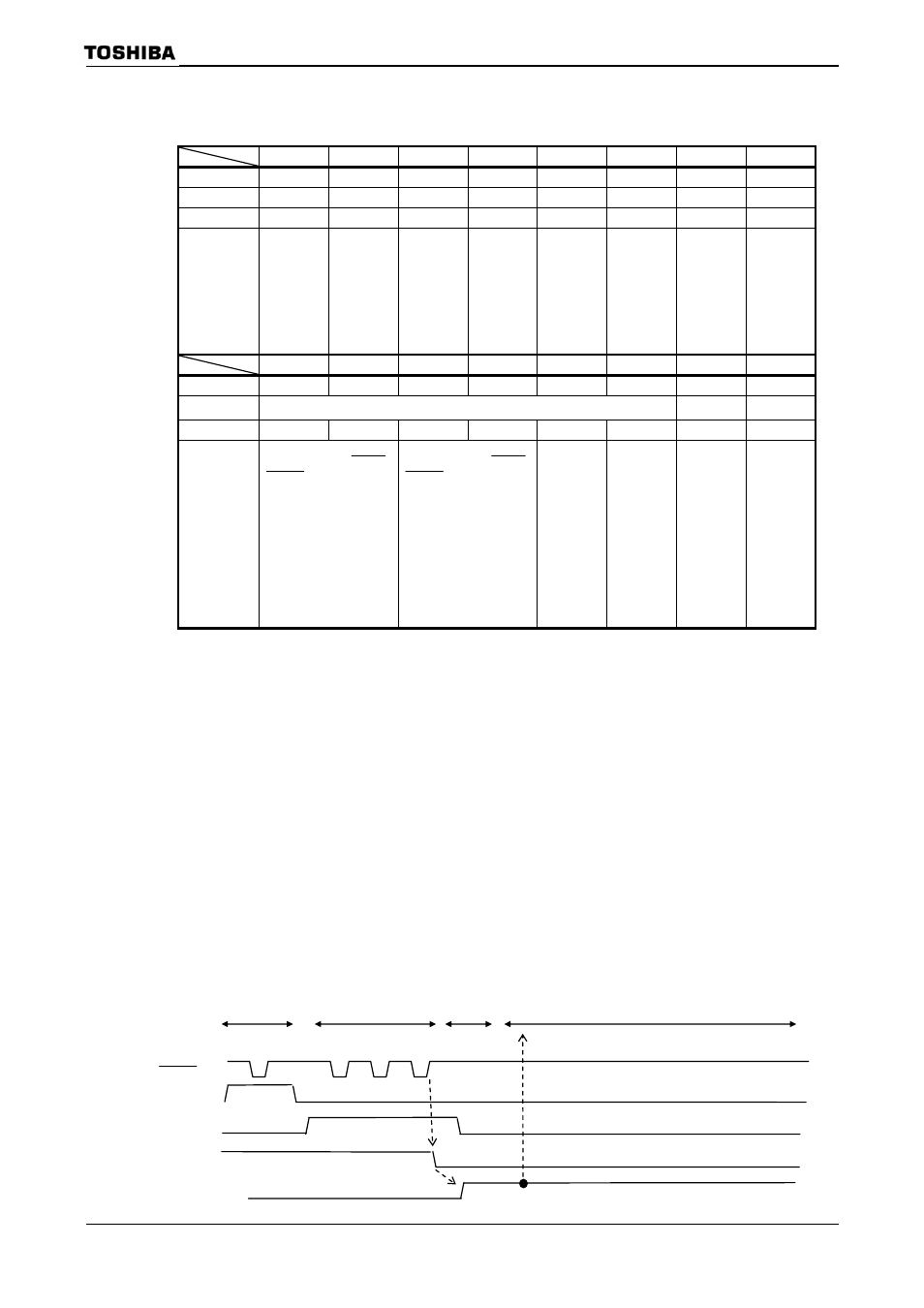
This bit is used to check the state of the NAND Flash memory (NDR/B pin). It is set to “1”
when the NAND Flash is “busy” and to “0” when it is “ready”.
Since the NDFC incorporates a noise filter of several states, a change in the NDR/B pin
state is reflected on the
delay time by software (e.g. ten NOP instructions) before checking this flag.
NDFMCR0
(08C0H)
Read-modify-
write
instructions
cannot be
used.
(08C1H)
Read-modify-
write
instructions
cannot be
used.
Address input
Read
command
Delay
time
Sensing
NDWE pin
NDCLE pin
NDALE pin
NDR/B pin