Toshiba H1 Series User Manual
Page 342
TMP92CZ26A
92CZ26A-339
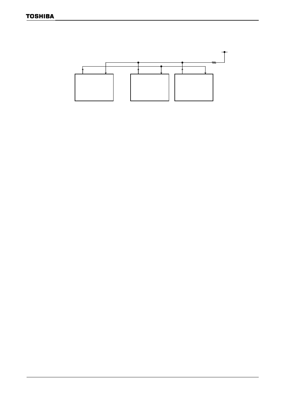
Setting example: To link two slave controllers serially with the master controller using the
internal clock f
IO
as the transfer clock.
• Setting the master controller
• Setting the slave controller
Main routine
P9CR
← X X X X X − 0 1
P9FC
← − − X X X − X 1
P9FC2
← X X X X X X X 1
Select P91 and P90 to function as the RXD0 and TXD0 pins
respectively (open-drain output).
INTES0
← X 1 0 0 X 1 0 0
Enable INTRX0 and INTTX0.
SC0MOD0
← 0 0 1 1 1 1 1 0
Set
SYS
as
the transfer clock.
Interrupt routine (INTRX0)
Acc
← SC0BUF
if Acc =Select code
Then SC0MOD0
← − − − 0 − − − − Clear
Main routine
P9CR
← X X X X X − 0 1
P9FC
← − − X X X − X 1
Set P90 and P91 to function as the TXD0 and RXD0 pins
respectively.
INTES0
← X 1 0 0 X 1 0 1
Enable the INTTX0 interrupt and set it to Interrupt Level 4.
Enable the INTRX0 interrupt and set it to Interrupt Level 5.
SC0MOD0
← 1 0 1 0 1 1 1 0
Set f
IO
as the transmission clock for 9-Bit UART Mode.
SC0BUF
← 0 0 0 0 0 0 0 1
Set the select code for slave controller 1.
Interrupt routine (INTTX0)
SC0MOD0
← 0 − − − − − − −
Set TB8 to 0.
SC0BUF
← * * * * * * * *
Set data for transmission.
TXD
RXD
Master
TXD
RXD
Slave1
TXD
RXD
Slave 2
Select code
00000001
Select code 00001010