Toshiba H1 Series User Manual
Page 107
TMP92CZ26A
92CZ26A-104
(3) CPU
+ LDMA + ARDMA
The SDRAM controller owns the bus not only when SDRAM is used as the LCD display
RAM but also when SDRAM is used as work, data, or stack area. The SDRAM controller
occupies the bus (ARDMA) while it refreshes SDRAM data by the auto refresh function.
No special consideration is needed for the ARDMA time normally as it ends within
several clocks per specified number of states. However, if the LCD controller occupies the
bus continuously, ARDMA cannot be executed at normal intervals and refresh data is
stored in a counter specifically provided in the SDRAM controller. In this case, ARDMA is
executed successively after the LCD controller releases the bus.
The priorities among the three bus masters should be set in the order of LCDC >
SDRAMC > CPU. The time the CPU stops operation while the LCD controller and SDRAM
controller are transferring data for one line is defined as “t
STOP
(LDMA ARDMA)”, which is
calculated as follows:
t
STOP
(LDMA ARDMA)
= t
STOP
(LDMA)[s]
− (t
STOP
(LDMA)[s] / AR interval [s]
× 2 / f
SYS
[Hz])
CPU bus stop rate
= t
STOP
(LDMA ARDMA)[s] / LHSYNC
[period: s]
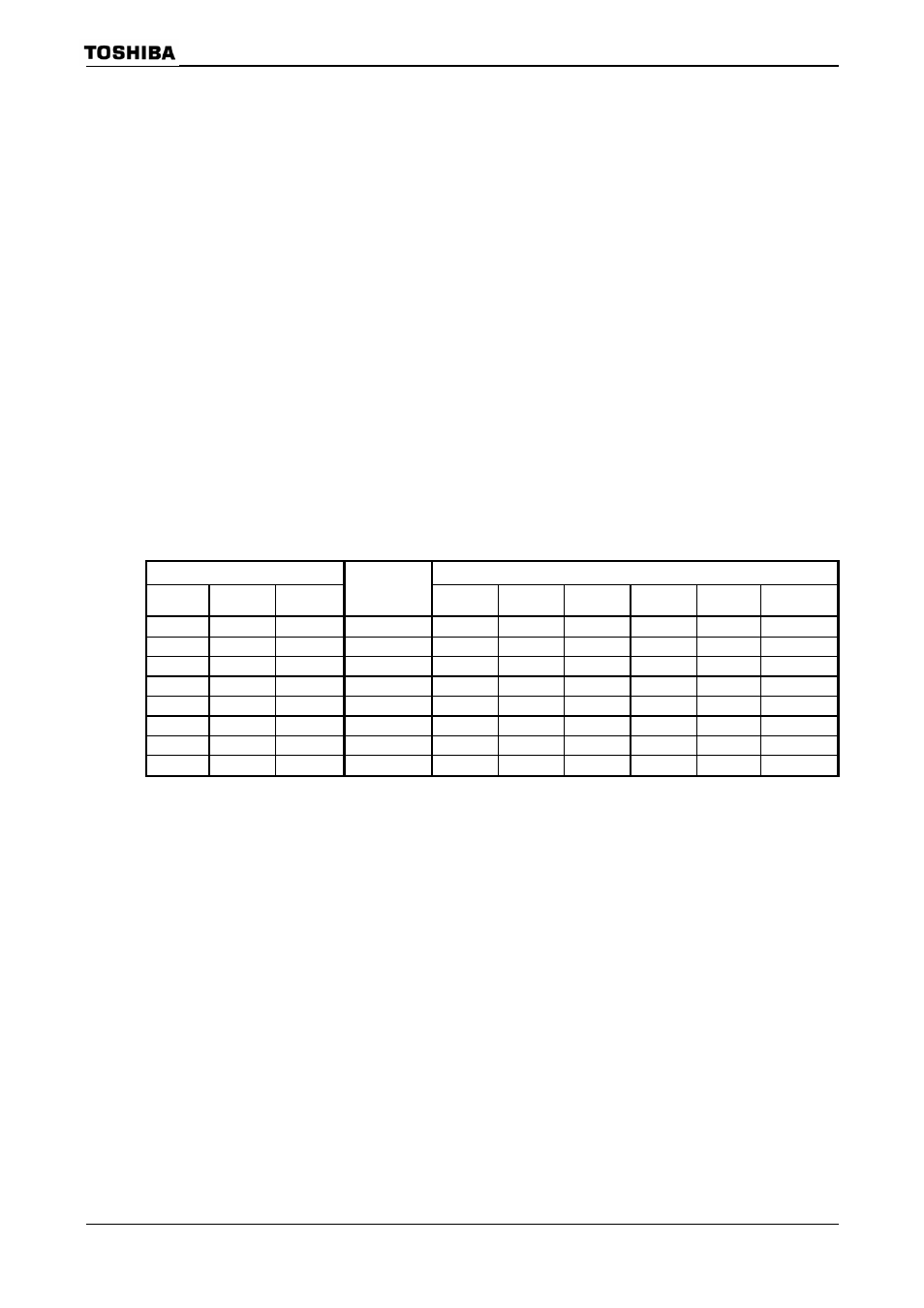
Auto Refresh Intervals
SDRCR
Frequency (System Clock)
SRS2 SRS1 SRS0
Auto Refresh
Interval
(states)
6 MHz
10MHz
20MHz
40MHz
60MHz
80MHz
0 0
0
47
7.8 4.7 2.4 1.18
0.78 0.59
0
0
1
78
13.0 7.8 3.9 1.95 1.30 0.98
0
1
0
156 26.0 15.6 7.8 3.90 2.60 1.95
0
1
1
312
52.0 31.2 15.6 7.80 5.20 3.90
1
0
0
468
78.0 46.8 23.4 11.70 7.80 5.85
1
0
1
624
104.0 62.4 31.2 15.60 10.40 7.80
1
1
0
936
156.0 93.6 46.8 23.40 15.60 11.70
1
1
1
1248 208.0 124.8 62.4 31.20 20.80 15.60
Unit: [
μs]