Tmp92cz26a – Toshiba H1 Series User Manual
Page 289
TMP92CZ26A
92CZ26A-286
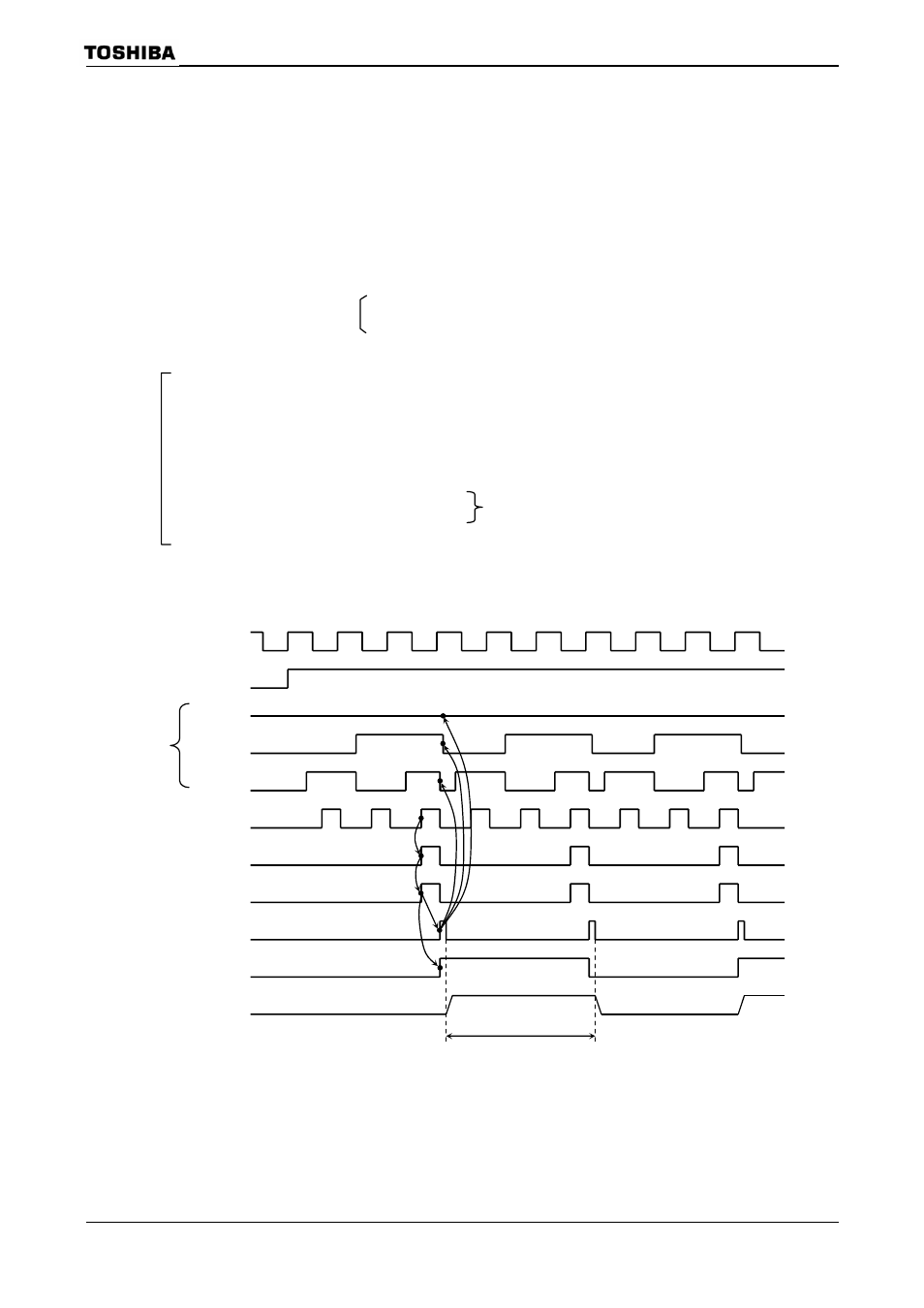
b. Generating a 50% duty ratio square wave pulse
The state of the timer flip-flop (TA1FF) is inverted at constant intervals and its
status output via the timer output pin (TA1OUT).
Example: To output a 3.2
μs square wave pulse from the TA1OUT pin at f
C
= 50 MHz,
use the following procedure to make the appropriate register settings. This
example uses TMRA1; however, either TMRA0 or TMRA1 may be used.
* Clock state
Clcok gear :
1/1
Prescaler of clock gear : 1/2
7 6 5 4 3
2
1
0
TA01RUN
← − X X X − −
0
−
Stop TMRA1 and clear it to “0”.
TA01MOD
← 0 0 X X 0 1
X
X
Select 8-bit timer mode and select
φT1 (0.16 μs at f
C
= 50
MHz) as the input clock.
TA1REG
← 0 0 0 0 1 0
1
0
Set the timer register to 3.2
μs ÷ φT1 ÷ 2 = 0AH
TA1FFCR
← X X X X 1 0
1
1
Clear TA1FF to “0” and set it to invert on the match detect
signal from TMRA1.
PM
← − X X X X −
0
X
PMFC
← − X X X X −
1
X
Set PM1 to function as the TA1OUT pin.
TA01RUN
← − X X X − 1
1
−
Start TMRA1 counting.
X: Don’t care,
−: No change
Figure 3.12.17 Square Wave Output Timing Chart (50% duty)
1.6
μs at f
C
= 50 MHz
0 1 2
3
0
1 2
3
0
1 2
3
0
φT1
TA01RUN
Bit7 to Bit2
Bit1
Bit0
INTTA1
TA1FF
TA1OUT
Up
counter
Comparator
timing
Comparator output
(Match detect)
UC1 clear