Toshiba H1 Series User Manual
Page 52
TMP92CZ26A
92CZ26A-49
(2) I/O register settings
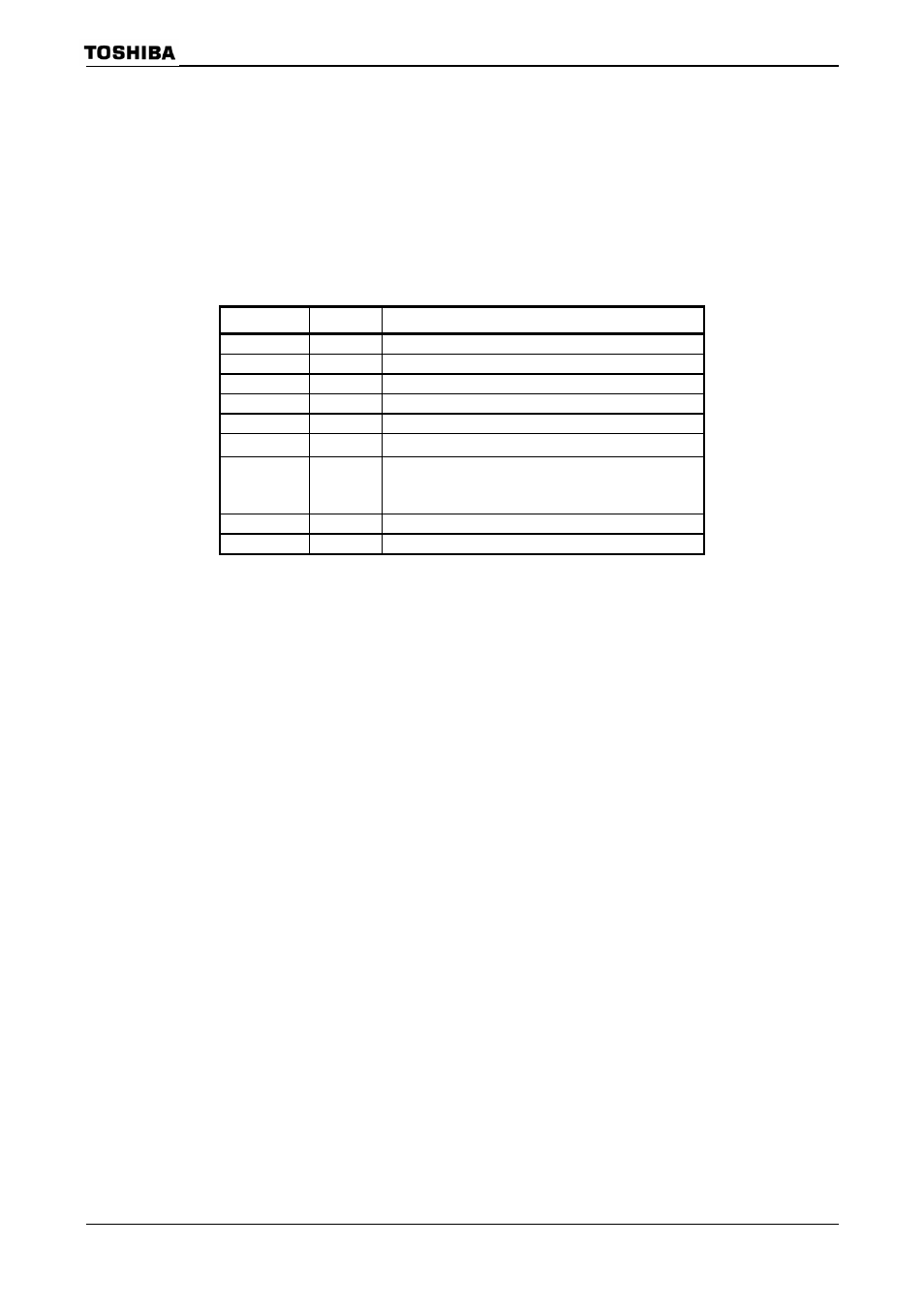
Table 3.4.5 shows the I/O registers that are set by the boot program.
After the boot sequence, if execution moves to an application system program
without a reset being asserted, the settings of these I/O registers must be taken into
account. Also note that the registers in the CPU and the internal RAM remain in the
state after execution of the boot program.
Table 3.4.5 I/O Register Settings by Boot Program
Register Name Set Value
Description
WDMOD
00H
Watchdog timer not active
WDCR
B1H
Watchdog timer disabled
SYSCR0
70H
High-frequency and low-frequency oscillators operating
SYSCR1
00H
Clock gear = 1/1
SYSCR2 2CH
Initial
value
PLLCR0
00H
PLL clock not used
PLLCR1 00H
or
60H
Normally PLL is disabled.
However, only in the case of booting via USB, PLL is
activated for USB.
INTEUSB
04H
USB interrupt level setting
INTETC01
44H
INTTC interrupt level setting
Note:
The values to be set in the I/O registers for
UART and USB are not described here. If these functions are
needed in a user program, set each I/O register as necessary.