5 internal boot rom control, Am1 am0 start mode – Toshiba H1 Series User Manual
Page 203
TMP92CZ26A
92CZ26A-200
3.8.5
Internal Boot ROM Control
This section describes about built-in boot ROM.
For the specification of S/W in boot ROM, refer to the section 3.4 boot ROM.
(1) BOOT mode
BOOT mode is started by following AM1 and AM0 pins condition with reset.
AM1 AM0
Start
mode
0
0
Don’t use this setting
0
1
Start with 16-bit data bus
1
0
Don’t use this setting
1
1
Start with boot (32-bit internal MROM)
(2)
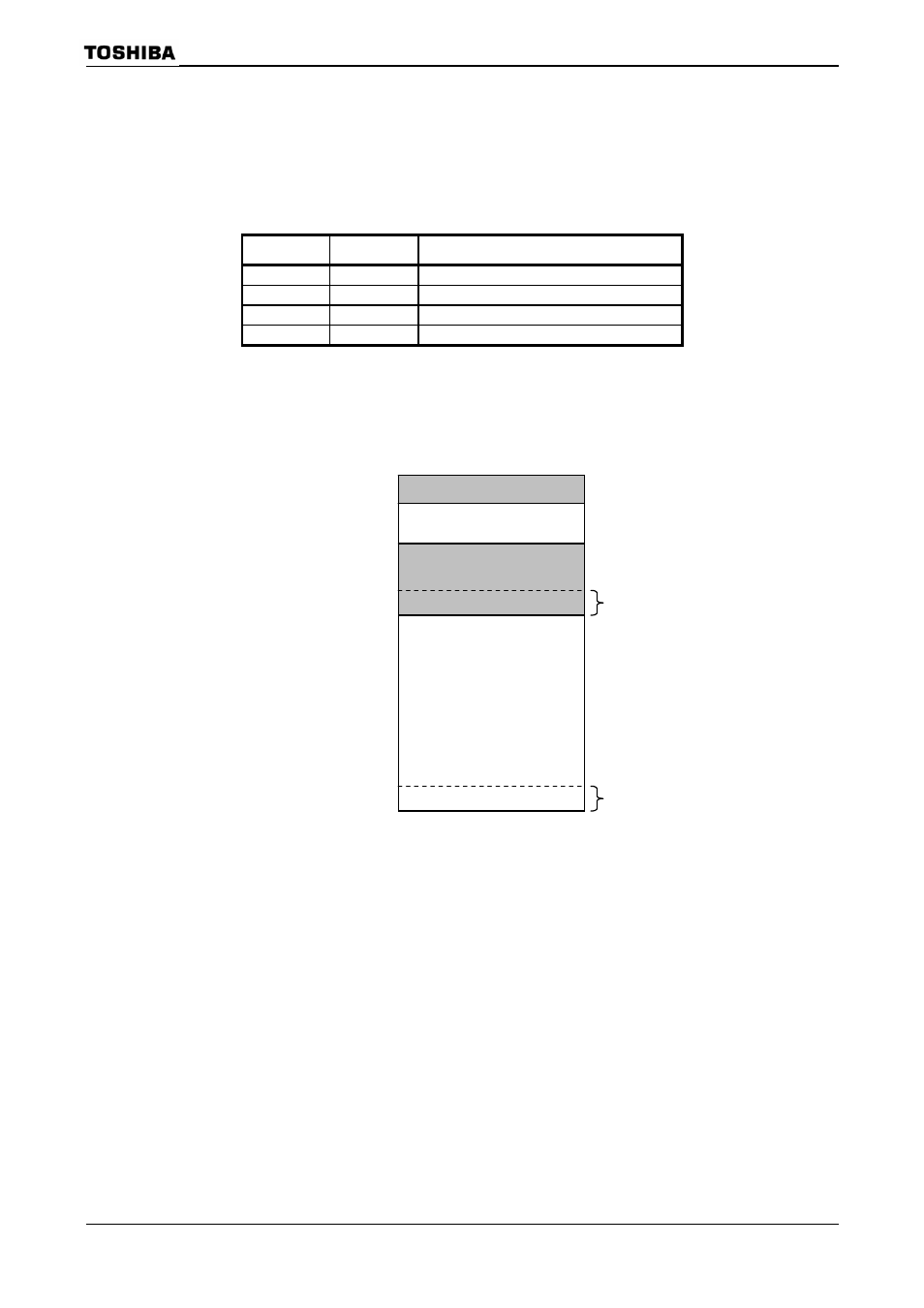
Boot ROM memory map
Boot ROM is consist of 8-Kbyte masked ROM and assigned 3FE000H to 3FFFFFH
address.
(3) Reset/interrupt address conversion circuit
Originally, reset/interrupt vector area is assigned FFFF00H to FFFFEFH ((A) area) in
TLCS-900/H1.
But because boot ROM is assigned to another area, reset/interrupt vector address
conversion circuit is prepared.
In BOOT mode, reset/interrupt vector area is assigned 3FFF00H to 3FFFEFH ((B) area)
area by it. And after boot sequence, its area can be changed to (A) area by setting
BROMCR
This BROMCR
this register has no meaning.
Note: The last 16-byte area (FFFFF0H to FFFFFFH) is reserved for an emulator. So, this area is not changed
by
Internal I/O , RAM
Internal boot ROM
(8 Kbytes)
04A000H
400000H
3FFF00H
FFFF00H
(B) Reset/Interrupt
Vector area
(256 bytes)
3FE000H
(A) Reset/Interrupt
Vector area
(256 bytes)
000000H