Toshiba H1 Series User Manual
Page 531
TMP92CZ26A
92CZ26A-528
2. LHSYNC
Signal
The period of the horizontal synchronization signal LHSYNC corresponds to one line
of display. The LHSYNC period is defined as an integral multiple of the reference
clock signal LCP0.
The LHSYNC period is defined as the product of the value set in LCDHSP
and the LCP0 clock period. The value to be set in LCDHSP
“segment size + number of dummy clocks” or larger for TFT. In the case of STN, the
minimum value of LCDHSP
Monochrome/grayscale
: (Segment size / 8)
+ number of dummy clocks
Color
: (Segment size
× 3 / 8) + number of dummy clocks
LHSYNC [s: period]
= LCP0 [s: period] × (
LCD LHSYNC Pulse Register
7 6 5 4 3 2 1 0
bit
Symbol
LH7 LH6 LH5 LH4 LH3 LH2 LH1 LH0
Read/Write W
After
reset
0 0 0 0 0 0 0 0
Function
LHSYNC period (bits 7-0)
7 6 5 4 3 2 1 0
bit
Symbol
LH15 LH14 LH13 LH12 LH11 LH10 LH9 LH8
Read/Write W
After
reset
0 0 0 0 0 0 0 0
Function
LHSYNC period (bits 15-8)
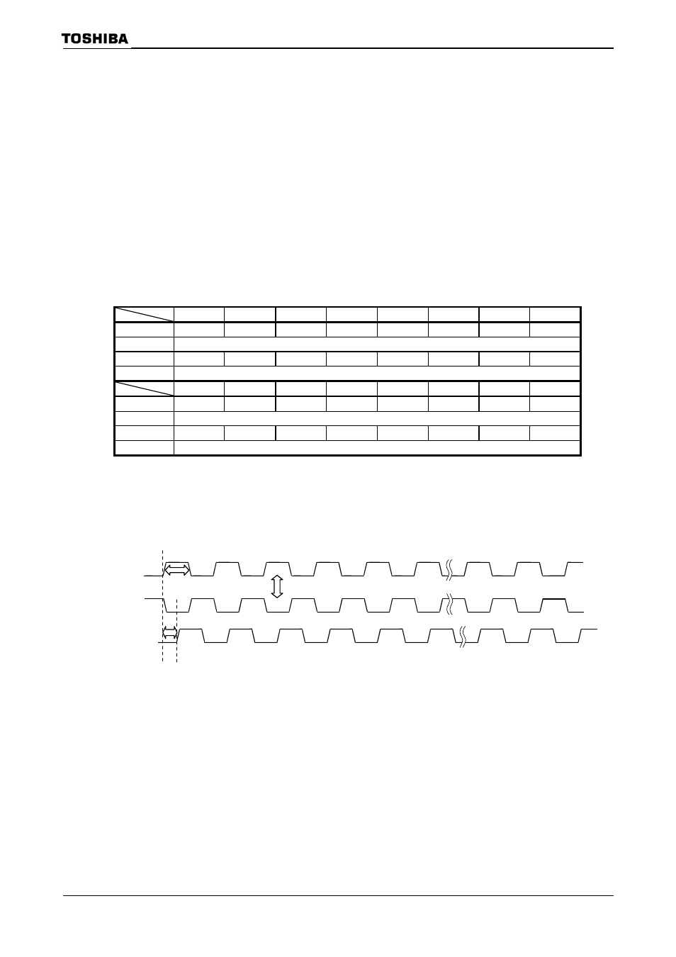
The enable width of the LHSYNC signal can be specified by LCDHSW
is also possible to set the delay time for the LVSYNC signal in units of LCP0 pulses.
LHSYNC signal
(Phase control)
(Enable width control)
(Delay control)
(028BH)
LCDHSP
(028AH)