Page rom read cycle, Tmp92cz26a, Ac measuring condition – Toshiba H1 Series User Manual
Page 653
TMP92CZ26A
92CZ26A-650
4.3.2
Page ROM Read Cycle
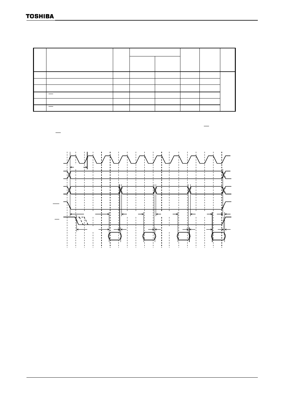
(1) 3-2-2-2 mode
Variable
Parameter Symbol
Min Max
80 MHz 60 MHz Unit
1 System clock period ( = T)
t
CYC
12.5 266.6
12.5
16.6
2 A0,
A1
→ D0 ~ D15 input
t
AD2
2.0T
− 18
7
15.2
3 A2 ~ A23
→ D0 ~ D15 input
t
AD3
3.0T
− 18
19.5
31.8
4
RD
falling
→ D0 ~ D15 input
t
RD3
2.5T
− 18 13 24
5 A0 ~ A23 Invalid → D0 ~ D15 hold
t
HA
0
0 0
6
RD
rising
→ D0 ~ D15 hold
t
HR
0
0 0
ns
AC measuring condition
Note: The (a), (b) and (c) of “Symbol” in above table depend on the falling timing of
RD
pin. The falling timing of
RD
pin is set by MEMCR0
correspond with (a) in above table, and “01” is (b), “10” is (c).
SDCLK
A2~A23
A0~A1
2
CS
RD
D0~D15
+0
+1
+2
+3
Data
input
Data
input
Data
input
Data
input
t
AD3
t
AD2
t
AD2
t
AD2
t
HA
t
HR
t
RD3
t
HA
t
HA
t
HA
t
CYC