Toshiba H1 Series User Manual
Page 294
TMP92CZ26A
92CZ26A-291
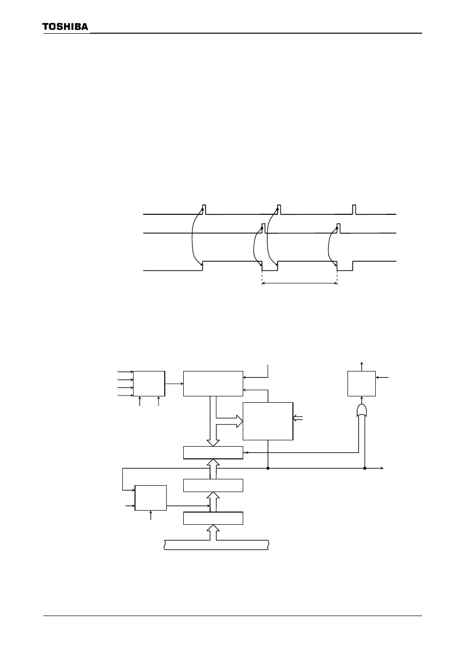
(4) 8-bit PWM (Pulse width modulation) output mode
This mode is only valid for TMRA0. In this mode, a PWM pulse with the maximum
resolution of 8 bits can be output.
When TMRA0 is used the PWM pulse is output on the TA1OUT pin (Shared with
PM1). TMRA1 can also be used as an 8-bit timer.
The timer output is inverted when the up counter (UC0) matches the value set in
the timer register TA0REG or when 2
n
counter overflow occurs (n
= 6, 7 or 8 as
specified by TA01MOD
n
counter
overflow occurs.
The following conditions must be satisfied before this PWM mode can be used.
Value set in TA0REG < Value set for 2
n
counter overflow
Value set in TA0REG
≠ 0
Figure 3.12.23 8-Bit PWM Waveforms
Figure 3.12.24 shows a block diagram representing this mode.
Figure 3.12.24 Block Diagram of 8-Bit PWM Mode
Selector
8-bit up counter
(UC0)
Comparator
TA0IN
φT1
φT4
φT16
TA01MOD
TA1FF
TA0REG
Register buffer
Selector
TA01RUN
TA0REG-WR
TA01RUN
TA1OUT
TA1FFCR
Shift trigger
Internal data bus
Clear
2
n
overflow
control
INTTA0
TA01MOD
Overflow
Inversion
TA0REG and
UC0 match
TA1OUT
t
PWM
(PWM cycle)
2
n
overflow
(INTTA0 interrupt)