Tmp92cz26a, Table 3.12.3 pwm cycle – Toshiba H1 Series User Manual
Page 296
TMP92CZ26A
92CZ26A-293
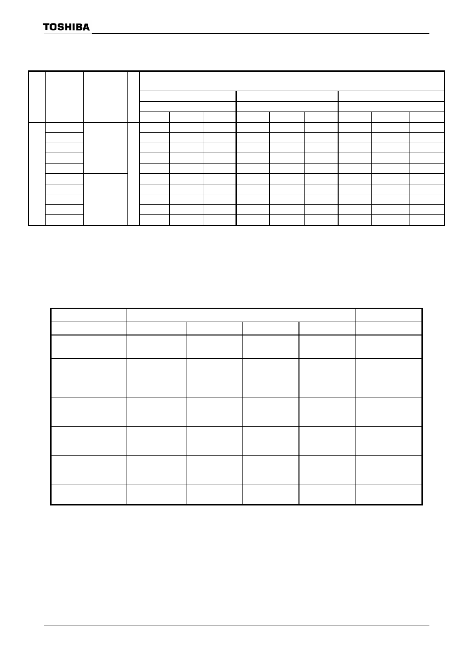
Table 3.12.3 PWM Cycle
PWM cycle
TAxxMOD
2
6
(x64)
2
7
(x128) 2
8
(x256)
TAxxMOD
Clock
gear
selection
SYSCR1
Prescaler of
clock gear
SYSCR0
φT1(x2)
φT4(x8)
φT16(x32)
φT1(x2)
φT4(x8)
φT16(x32) φT1(x2)
φT4(x8)
φT16(x32)
000(x1)
512/fc 2048/fc 8192/fc 1024/fc 4096/fc 16384/fc
2048/fc 8192/fc 32768/fc
001(x2)
1024/fc 4096/fc 16384/fc
2048/fc 8192/fc 32768/fc
4096/fc 16384/fc 65536/fc
010(x4)
2048/fc 8192/fc 32768/fc
4096/fc 16384/fc 65536/fc
8192/fc 32768/fc 131072/fc
011(x8)
4096/fc 16384/fc
65536/fc
8192/fc 32768/fc 131072/fc
16384/fc 65536/fc 262144/fc
100(x16)
0(x2)
8192/fc 32768/fc
131072/fc
16384/fc
65536/fc 262144/fc
32768/fc 131072/fc 524288/fc
000(x1)
2048/fc 8192/fc 32768/fc
4096/fc 16384/fc 65536/fc
8192/fc 32768/fc 131072/fc
001(x2)
4096/fc 16384/fc
65536/fc
8192/fc 32768/fc 131072/fc
16384/fc 65536/fc 262144/fc
010(x4)
8192/fc 32768/fc
131072/fc
16384/fc
65536/fc 262144/fc
32768/fc 131072/fc 524288/fc
011(x8)
16384/fc 65536/fc
262144/fc
32768/fc
131072/fc
524288/fc
65536/fc 262144/fc 1048576/fc
1/fc
100(x16)
1(x8)
x
2
32768/fc 131072/fc
524288/fc
65536/fc
262144/fc
1048576/fc 131072/fc 524288/fc 2097152/fc
(5) Settings for each mode
Table 3.12.4 shows the SFR settings for each mode.
Table 3.12.4 Timer Mode Setting Registers
Register Name
TA01MOD
TA1FFCR
TA1FFIS
Function
Timer Mode
PWM Cycle
Upper Timer Input
Clock
Lower Timer
Input Clock
Timer F/F Invert Signal
Select
8-bit timer
× 2 channels
00
−
Lower timer
match
φT1, φT16, φT256
(00, 01, 10, 11)
External clock
φT1, φT4, φT16
(00, 01, 10, 11)
0: Lower timer output
1: Upper timer output
16-bit timer mode
01
−
−
External clock
φT1, φT4, φT16
(00, 01, 10, 11)
−
8-bit PPG
× 1 channel
10
−
−
External clock
φT1, φT4, φT16
(00, 01, 10, 11)
−
8-bit PWM
× 1 channel
11
2
6
, 2
7
, 2
8
(01, 10, 11)
−
External clock
φT1, φT4, φT16
(00, 01, 10, 11)
−
8-bit timer
× 1 channel
11
−
φT1, φT16, φT256
(01, 10, 11)
−
Output disabled
−: Don’t care