4 switch settings, Table 2-5, Switch sw1 settings – Artesyn ATCA-7480 Installation and Use (February 2015) User Manual
Page 51: Figure 2-3, Switch location (bottom side of the blade), Hardware preparation and installation
Hardware Preparation and Installation
ATCA-7480 Installation and Use (6806800T17A)
51
2.4
Switch Settings
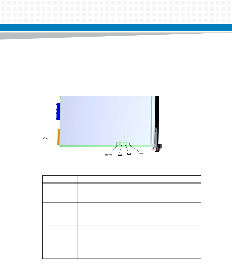
All mechanical switches are OFF in their default configuration. Switch selection used only for
debugging are grouped in separate devices, which are not assembled in volume production.
Switches reside on the component side 1 and are not covered by any other component. Their
location is shown in the following figure:
Figure 2-3
Switch Location (Bottom Side of the Blade)
Table 2-5 Switch SW1 settings
Switch
Function
Default
SW1.1
A2F200 JTAG_SEL strap
OFF= JTAG to Fabric (Default)
ON= JTAG to CPU-Core
OFF A2F200
JTAGSEL
SW1.2
BIOS Image Swap
OFF
Default Image
ON=secondary
Image in 16MB
device
SW1.3
TSOP or Debug-Socket SPI Boot
select
OFF= Boot from TSOP SPI Flash (either
Default/Recovery)
ON = Boot from Debug Socket SPI
Flash
OFF
Boot from BIOS
Socket