19 pch output enable register, 20 rtm spi interface registers, Table 5-78 – Artesyn ATCA-7480 Installation and Use (February 2015) User Manual
Page 159: Pch output enable register, Maps and registers

Maps and Registers
ATCA-7480 Installation and Use (6806800T17A)
159
5.1.19 PCH Output Enable Register
The output signals, PCH_RCIN_, PCH_SCI_ and PCH_PSTATE_ are connected to the GPIO Pins
of the PCH. After power-up, the PCH drives these signals. To avoid signal contention, the
outputs are tri-stated. After software has configured the PCH GPIO pins as inputs, the
corresponding outputs can be enabled with this Register.
5.1.20 RTM SPI Interface Registers
The signals, RTM_SPI_SCK, RTM_SPI_SS_, RTM_SPI_MISO and RTM_SPI_MOSI are used to
support a SPI master protocol. The signal, RTM_SPI_MISO is also used to signal an ARTM
interrupt to the base board. See Chapter 5.18.4 RTM Interrupt Status Register.
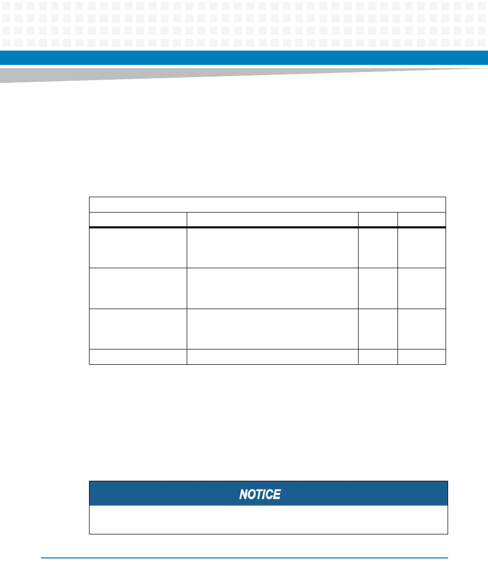
Table 5-78 PCH Output Enable Register
Address Offset: 0x41
Bit
Description
Default
Access
0
PCH_RCIN_ enable:
0: Disabled. Signal is tri-state
1: Enabled. Drive pch_rcin
0
LPC: r/w
1
PCH_SCI_ enable:
0: Disabled. Signal is tri-state
1: Enabled. Drive pch_sci
0
LPC: r/w
2
PCH_PSTATE_ enable:
0: Disabled. Signal is tri-state
1: Enabled. Drive pch_pstate
0
LPC: r/w
7:3
Reserved
0
0
At the moment there is no ARTM with an SPI interface defined.
