Table 5-47, Payload power failure state register, Table 5-48 – Artesyn ATCA-7480 Installation and Use (February 2015) User Manual
Page 134: Payload power failure states, Table, Maps and registers
Maps and Registers
ATCA-7480 Installation and Use (6806800T17A)
134
The power failing state is kept until payload power is turned off:
Manual Powering: Setting the switch, SW100.1 from ON to OFF.
IPMC controlled powering: The IPMC shut down the payload power (signal
IPMC_VP48_EN_ is deasserted)
The table below shows all possible failing states and their coding. When the board is powered
via switch SW100.1, the debug mode is enabled, where some timeouts are disabled. With
debug mode enabled, the failure transition to SHUTDOWN is disabled for the states
CLK_ENABLE, WAIT_100MS and S0. Nevertheless the failing state and the failing causes are
latched.
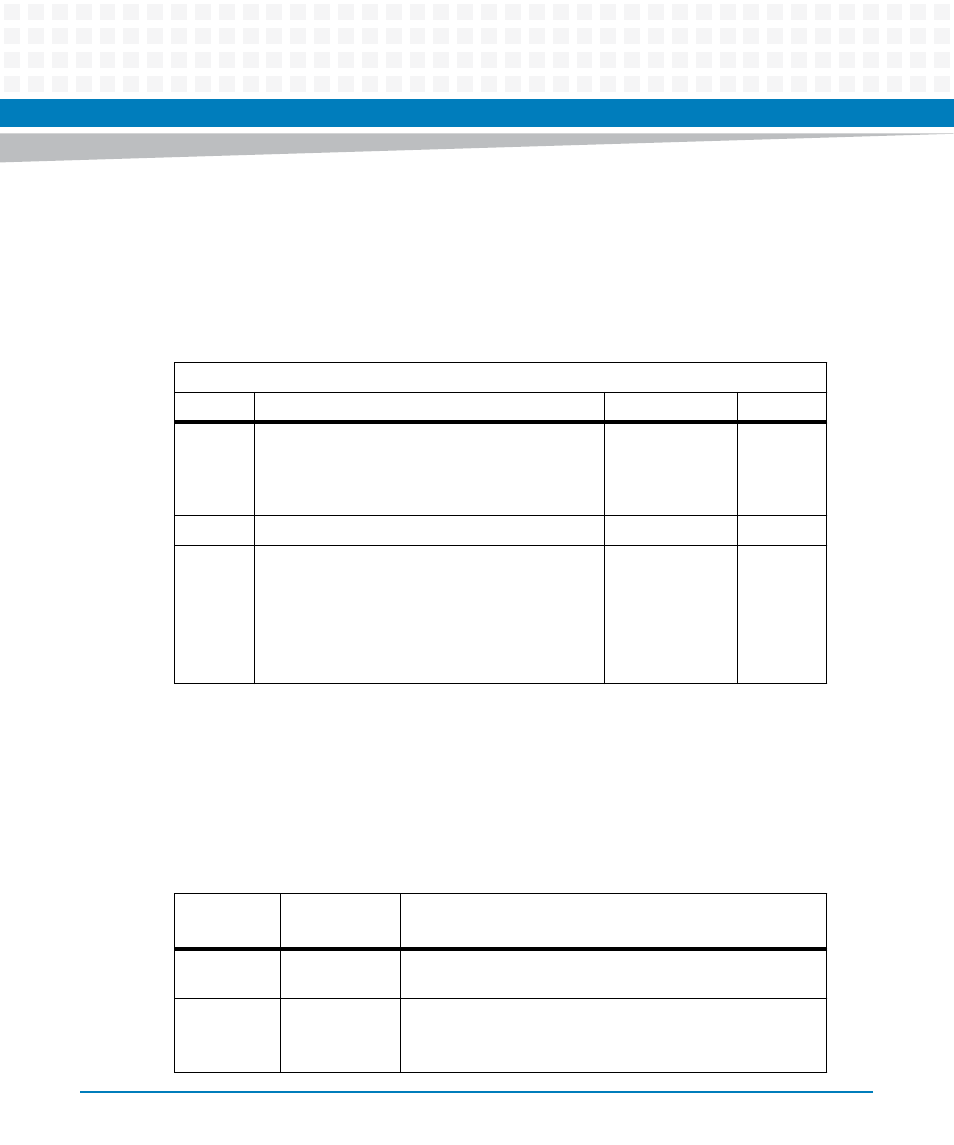
Table 5-47 Payload Power Failure State Register
Address Offset: 0x0A
Bit
Description
Default
Access
4:0
Payload Power Failure State. Latched last Payload
Power state when failure occurred. See
Note: Only valid with Payload Failure (Bit 7) is set.
PWR_GOOD:0
IPMC: r
6:5
Reserved
0
IPMC: r
7
Payload Power Failure. Payload Power state
machine sampled a failing Payload Power status:
0: No Payload Power Failure. Normal Payload
operation
1: Payload Power failure. Payload Power failure
detected.
PWR_GOOD:0
IPMC: r
Table 5-48 Payload Power Failure States
State
Coding
State
Name
Description
0x1
CLK_ENABLE
One or more voltages have failed, which have been already
enabled and sampled good.
0x4
S0
One or more voltages have failed, which have been already
enabled and sampled good.
Other cause: Thermtrip