Asynchronous mode – Zilog Z80230 User Manual
Page 99
SCC/ESCC
User Manual
UM010903-0515
Data Communication Modes
92
Asynchronous Mode
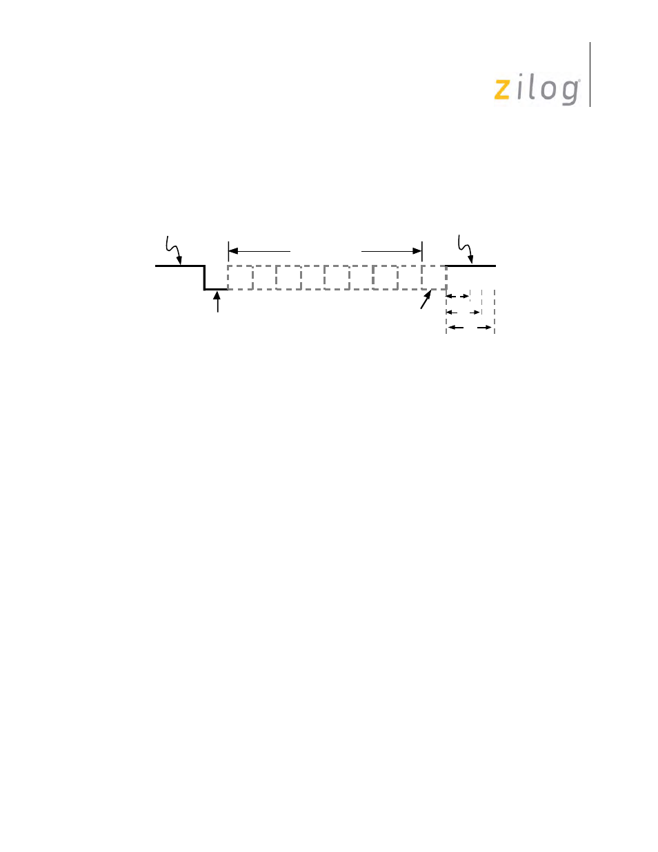
In asynchronous communications, data is transferred in the format displayed in
Asynchronous Message Format
The transmission of a character begins when the line makes a transition from the 1 state (or
MARK condition) to the 0 state (or SPACE condition). This transition is the reference by which
the character’s bit cell boundaries are defined. Though the transmitter and receiver have no com-
mon clock signal, they must be at the same data rate so that the receiver can sample the data in the
center of the bit cell.
The SCC also supports Isochronous mode, which is the same as Asynchronous except that the
clock is the same rate as the data. This mode is selected by selecting x1 clock mode in WR4 (D7 &
D6=0). Using this mode typically requires that the transmit clock source be transmitted along with
the data, or that the clock be synchronized with the data.
The character can be broken up into four fields:
•
Start bit - signals the beginning of a character frame.
•
Data field - typically 5-8 bits wide.
•
Parity bit - optional error checking mechanism.
•
Stop bit(s) - Provides a minimum interval between the end of one character and the begin-
ning of the next.
Generation and checking of parity is optional and is controlled by WR4 D1 & D0. WR4 bit D0 is
used to enable parity. If WR4 bit D1 is set, even parity is selected and if D1 is reset, odd parity is
selected. For even parity, the parity bit is set/reset so that the data byte plus the parity bit contains
an even number of 1s. For odd parity, the parity bit is set/reset such that the data byte plus the par-
ity bit contains an odd number of 1s.
Idle State
of Line
LSB
1
0
Start
Bit
Parity
Bit
Data Field
Stop
Bit(s)
1.5
1
2