Zilog Z80230 User Manual
Page 242

SCC/ESCC
User Manual
UM010903-0515
Application Notes
235
interrupt daisy chain to settle so the device requesting the interrupt places its interrupt vector onto
the data bus.
The Shift Register allows enough time delay from the generation of /INTACK before it generates /
SCCRD. During this delay, it places the Z180 into a Wait state until the valid interrupt vector is
placed onto the data bus. If the time between these two signals is not enough for daisy chain set-
tling, more time is added by taking /SCCRD and /WAIT from a later position on the Shift Register.
If there is a requirement for more wait states, the time is calculated by PHI cycles.
Using EPLD
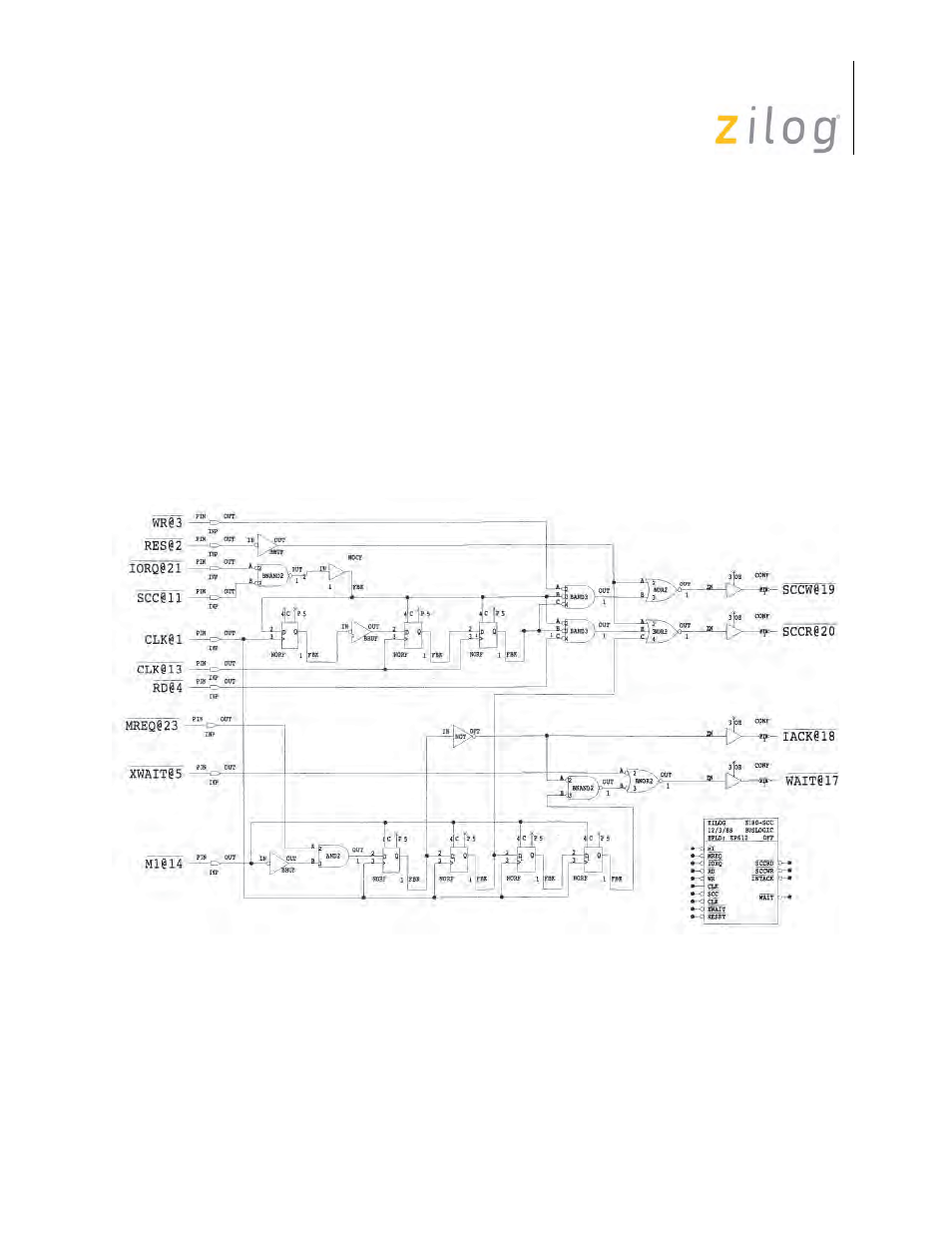
Figure and Figure on page 236 display the logic using either random gate logic to EPLD is to dis-
assemble MSIs’ logic EPLD or the circuit of this system. The EPLD is ALTERA into SSI level,
and then simplify the logic. 610 which is a 24-Pin EPLD. The method to convert random gate
logic to EPLD is to disassemble MSIs’ logic into SSI level, and then simplify the logic.
ELPD Circuit Implementation
