And modes) – Zilog Z80230 User Manual
Page 157
SCC/ESCC
User Manual
UM010903-0515
Register Descriptions
150
The address recognition logic of the receiver is modified in SDLC mode if this bit is set to 1, i.e.,
only the four most significant bits of WR6 must match the receiver address. This procedure allows
the SCC to receive frames from up to 16 separate sources without programming WR6 for each
source (if each station address has the four most significant bits in common). The address field in
the frame is still eight bits long. Address FFH is always recognized as a global address.
The bit is ignored in SDLC mode if Address Search mode has not been selected.
Bit 0: Receiver Enable
When this bit is set to 1, receiver operation begins. This bit should be set only after all other
receiver parameters are established and the receiver is completely initialized. This bit is reset by a
channel or hardware reset command, and it disables the receiver.
Write Register 4 (Transmit/Receive Miscellaneous Parameters and Modes)
WR4 contains the control bits for both the receiver and the transmitter. These bits should be set in
the transmit and receiver initialization routine before issuing the contents of WR1, WR3, WR6,
and WR7. Bit positions for WR4 are displayed in
. On the ESCC and 85C30, with the
Extended Read option enabled, this register is read as RR4.
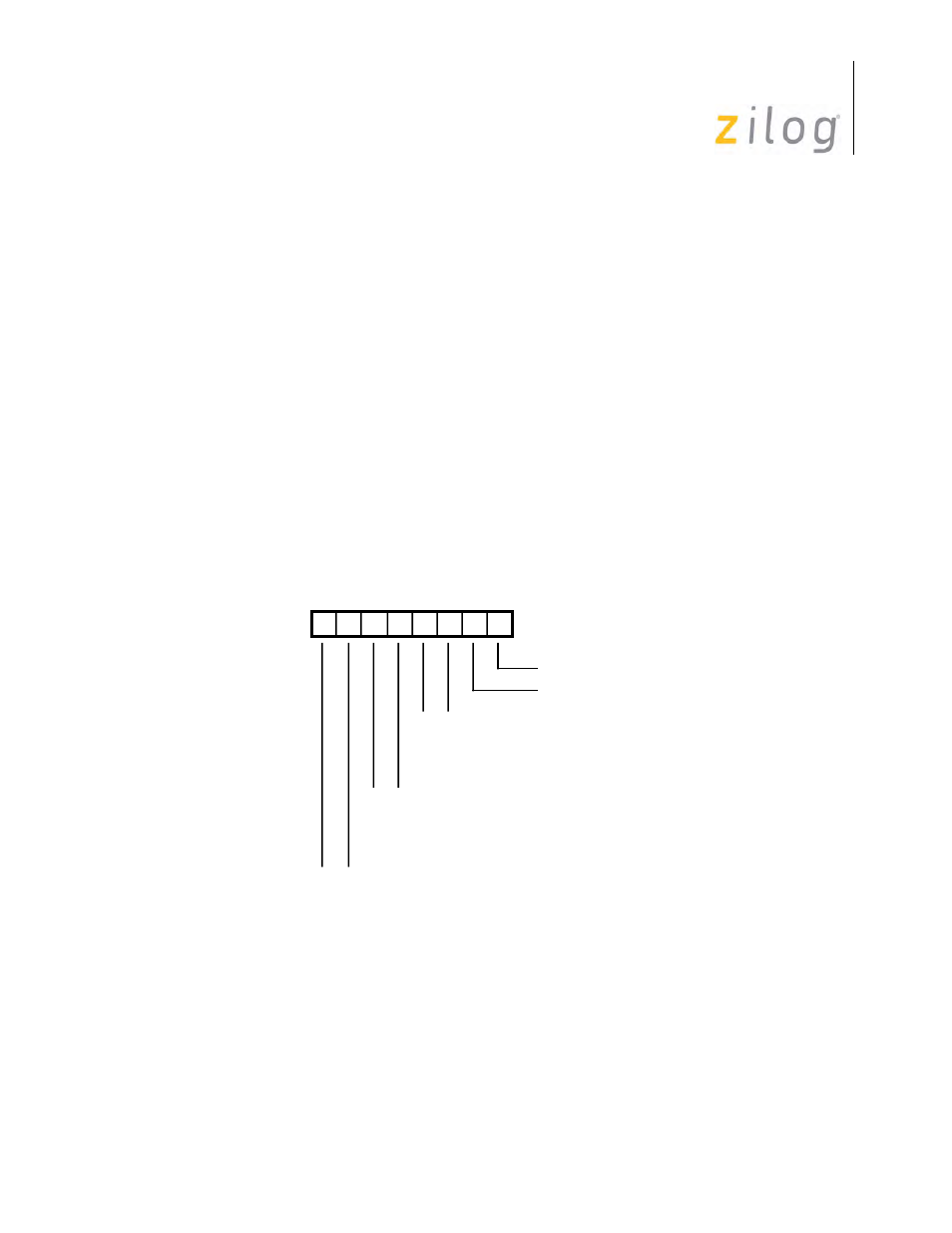
Write Register 4
Bits 7 and 6: Clock Rate bits 1 and 0
These bits specify the multiplier between the clock and data rates. In synchronous modes, the 1X
mode is forced internally and these bits are ignored unless External Sync mode has been selected.
D7 D6 D5 D4 D3 D2 D1 D0
Write Register 4
Parity Enable
0 0 X1 Clock Mode
0 1 X16 Clock Mode
1 0 X32 Clock Mode
1 1 X64 Clock Mode
Parity EVEN//ODD
0 0 Sync Modes Enable
0 1 1 Stop Bit/Character
1 0 1 1/2 Stop Bits/Character
1 1 2 Stop Bits/Character
0 0 8-Bit Sync Character
0 1 16-Bit Sync Character
1 0 SDLC Mode (01111110 Flag)
1 1 External Sync Mode