Zilog Z80230 User Manual
Page 231
SCC/ESCC
User Manual
UM010903-0515
Application Notes
224
Interrupt Control
/INTACK
Interrupt Acknowledge (input, active Low). This signal shows an Interrupt Acknowledge cycle
which combines with /RD to gate the interrupt vector onto the data bus.
/INT
Interrupt request (output, open-drain, active Low).
IEI
Interrupt Enable In (input, active High).
IEO
Interrupt Enable Out (Output, active High).
These lines control the interrupt daisy chain for the peripheral interrupt response.
SCC I/O Operation
The SCC generates internal control signals from /RD or /WR. Since PCLK has no required phase
relationship to /RD or /WR, the circuitry generating these signals provides time for meta stable
conditions to disappear.
The SCC starts the different operating modes by programming the internal registers. Accessing
these internal registers occurs during I/O Read and Write cycles, described below.
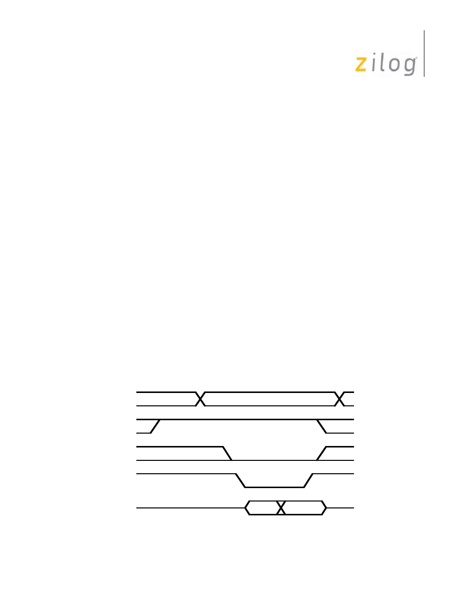
Read Cycle Timing
Figure displays the SCC Read cycle timing. All register addresses and /INTACK are stable
throughout the cycle. The timing specification of SCC requires that the /CE signal (and address)
be stable when /RD is active
SCC Read Cycle Timing
Address
/INTACK
/CE
/RD
D7-D0
Data Valid
Address Valid