Zilog Z80230 User Manual
Page 119

SCC/ESCC
User Manual
UM010903-0515
Data Communication Modes
112
and begins sending sync characters. Beyond this point the receiver and transmitter are again com-
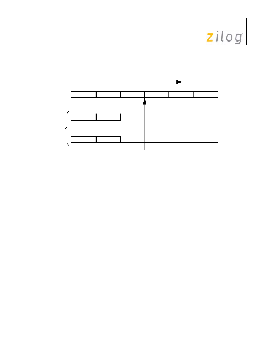
pletely independent, except that the character boundaries are now aligned (
).
Transmitter to Receiver Synchronization
There are several restrictions on the use of this feature in the SCC. First, it only works with 6-bit,
8-bit or 16-bit sync characters. The data character length for both the receiver and the transmitter
must be six bits with 6-bit sync character, and eight bits with an 8-bit or 16-bit sync character. Of
course, the receive and transmit clocks must have the same rate as well as the proper phase rela-
tionship.
A specific sequence of operations must be followed to synchronize the transmitter to the receiver.
Both the receiver and transmitter must have been initialized for operation in Synchronous mode
sometime in the past, although this initialization need not be redone each time the transmitter is
synchronized to the receiver. The transmitter is disabled by setting bit D3 of WR5 to 0. At this
point the transmitter will send continuous 1s. If it is required that continuous 0s be transmitted, the
Send Break bit (D4) in WR5 is set to 1. The transmitter is now idling but is still placed in the trans-
mitter to receiver synchronization mode. This is accomplished by setting the Loop Mode bit (D1)
in WR10 and then enabling the transmitter by setting bit D3 of WR5 to 1. At this point, the proces-
sor should set the Go Active on Poll bit (D4) in WR10. The final step is to force the receiver to
search for sync characters. If the receiver is currently disabled, the receiver enters Hunt mode
when it is enabled, by setting bit D0 of WR3 to 1. If the receiver is already enabled, it is placed in
Hunt mode by setting bit D4 of WR3 to 1. Once the receiver leaves Hunt mode, the transmitter is
activated on the following character boundary.
Receiver Leaves Hunt
Sync
Sync
RxD
TxD
Sync
Sync
Direction of Message Flow
