Zilog Z80230 User Manual
Page 169
SCC/ESCC
User Manual
UM010903-0515
Register Descriptions
162
The Vector Includes Status Bit controls whether or not the SCC includes status information in the
vector it places on the bus in response to an interrupt acknowledge cycle. If this bit is set, the vec-
tor returned is variable, with the variable field depending on the highest priority IP that is set.
on page 153 lists the encoding of the status information. This bit is ignored if the No Vector
(NV) bit is set.
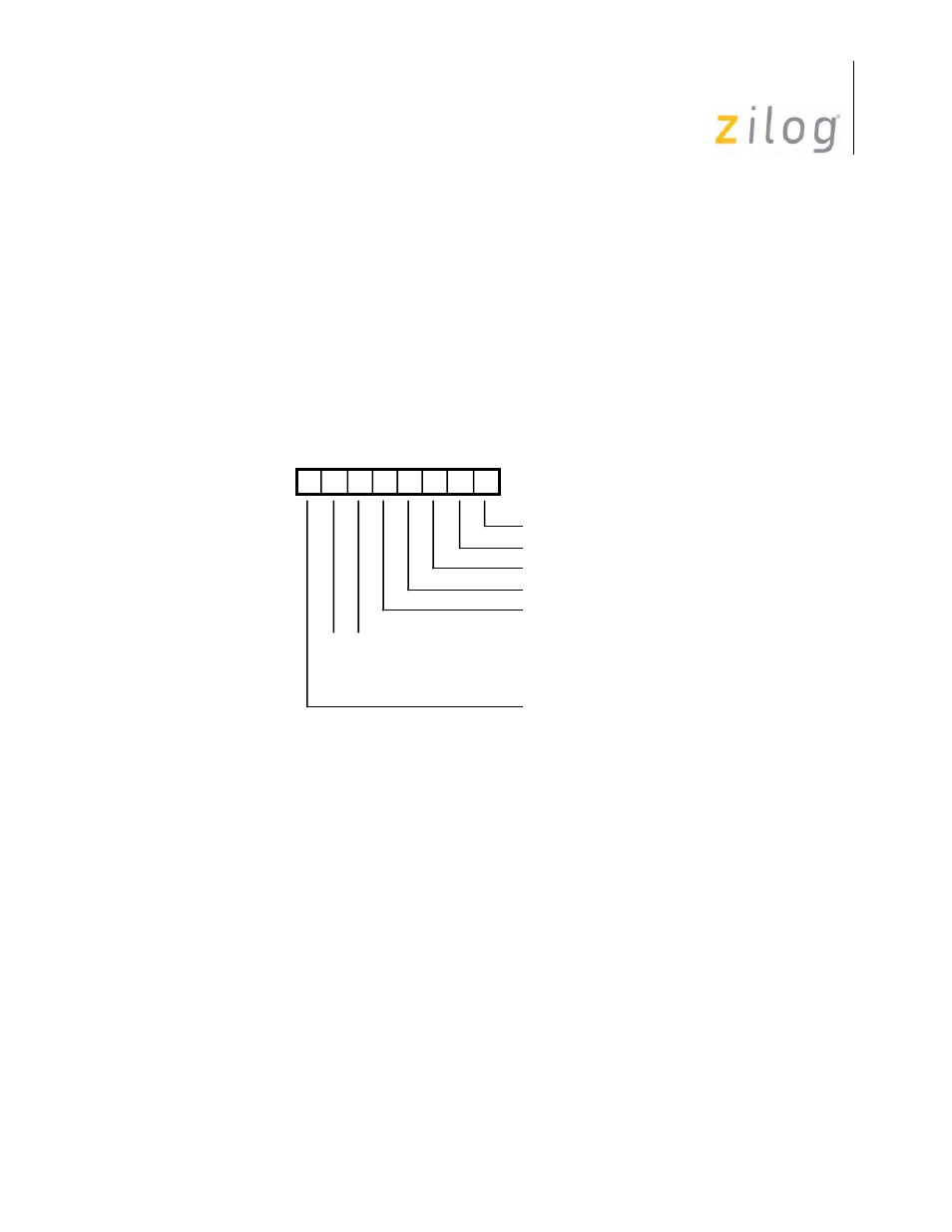
Write Register 10 (Miscellaneous Transmitter/Receiver Control Bits)
WR10 contains miscellaneous control bits for both the receiver and the transmitter. Bit positions
for WR10 are displayed in
. On the ESCC and 85C30 with the Extended Read option
enabled, this register may be read as RR11.
Write Register 10
Bit 7: CRC Presets I/O select bit
This bit specifies the initialized condition of the receive CRC checker and the transmit CRC gener-
ator. If this bit is set to 1, the CRC generator and checker are preset to 1. If this bit is set to 0, the
CRC generator and checker are preset to 0. Either option can be selected with either CRC polyno-
mial. In SDLC mode, the transmitted CRC is inverted before transmission, and the received CRC
is checked against the bit pattern 0001110100001111. This bit is reset by a channel or hardware
reset. This bit is ignored in Asynchronous mode.
Bits 6 and 5: Data Encoding select bits.
These bits control the coding method used for both the transmitter and the receiver, as listed in
on page 163. All of the clocking options are available for all coding methods. The DPLL in
the SCC is useful for recovering clocking information in NRZI and FM modes. Any coding
method can be used in X1 mode. A hardware reset forces NRZ mode. Timing for the various
modes is displayed in
D7 D6 D5 D4 D3 D2 D1 D0
Write Register 10
6-Bit//8-Bit Sync
0 0 NRZ
0 1 NRZI
1 0 FM1 (Transition = 1)
1 1 FM0 (Transition = 0)
Loop Mode
Abort//Flag On Underrun
Mark//Flag Idle
Go Active On Poll
CRC Preset I//O