Zilog Z80230 User Manual
Page 232
SCC/ESCC
User Manual
UM010903-0515
Application Notes
225
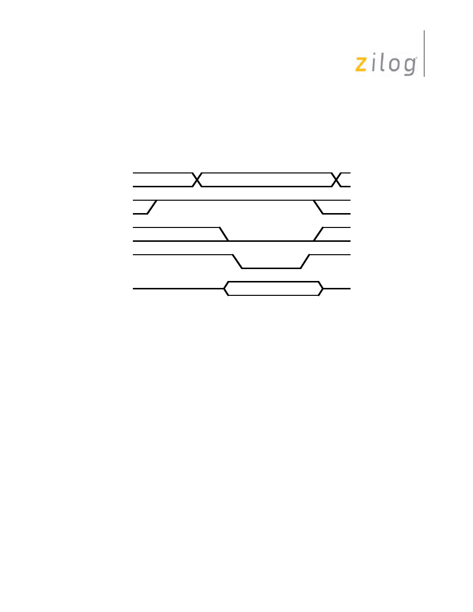
Write Cycle Timing
Figure on page 225 displays the SCC Write cycle timing. All register addresses and /INTACK are
stable throughout the cycle. The timing specification of the SCC requires that the /CE signal (and
address) be stable when /RD is active. Data is available to the SCC before the falling edge of
/WR and remains active until /WR goes inactive
SCC Write Cycle Timing
SCC Interrupt Operation
Understanding SCC interrupt operations requires a basic knowledge of the Interrupt Pending (IP)
and Interrupt Under Service (IUS) bits in relation to the daisy chain. The Z180 and SCC design
allow no additional interrupt requests during an Interrupt Acknowledge cycle. This permits the
interrupt daisy chain to settle, ensuring proper response of the interrupt device.
The IP bit sets in the SCC for CPU intervention requirements (that is, buffer empty, character
available, error detection, or status changes). The interrupt acknowledge cycle does not reset the
IP bit. The IP bit clears by a software command to the SCC, or when the action that generated the
interrupt ends, for example, reading a receive character for receive interrupt. Others are, writing
data to the transmitter data register, issuing Reset Tx interrupt pending command for Tx buffer
empty interrupt, etc.). After servicing the interrupt, other interrupts can occur.
The IUS bit means the CPU is servicing an interrupt. The IUS bit sets during an Interrupt
Acknowledge cycle if the IP bit sets and the IEI line is High. If the IEI line is Low, the IUS bit is
not set. This keeps the device from placing its vector onto the data bus.
The IUS bit clears in the Z80
®
peripherals by decoding the RETI instruction. A software com-
mand also clears the IUS bit in the Z80 peripherals. Only software commands clear the IUS bit in
the SCC.
Address
/INTACK
/CE
/WR
D7-D0
Data Valid
Address Valid