Zilog Z80230 User Manual
Page 47
SCC/ESCC
User Manual
UM010903-0515
Interfacing the SCC/ESCC
40
Master Interrupt Enable Bit
The Master Interrupt Enable (MIE) bit, WR9 D3, must be set to enable the SCC to generate inter-
rupts. The MIE bit should be set after initializing the SCC registers and enabling the individual
interrupt enables. The SCC requests an interrupt by asserting the /INT pin Low from its open-
drain state only upon detection that one of the enabled interrupt conditions has been detected.
Interrupt Enable Bit
The Interrupt Enable (IE) bits control interrupt requests from each interrupt source on the SCC. If
the IE bit is set to 1 for an interrupt source, that source may generate an interrupt request, provid-
ing all of the necessary conditions are met. If the IE bit is reset, no interrupt request is generated by
that source. The transmit interrupt IE bit is WR1 D1. The receive interrupt IE bits are WR1 D3 and
D4. The external status interrupts are individually enabled in WR15 with the master external status
interrupt enable in WR1 D0. Reminder: The MIE bit, WR9 D3, must be set for any interrupt to
occur.
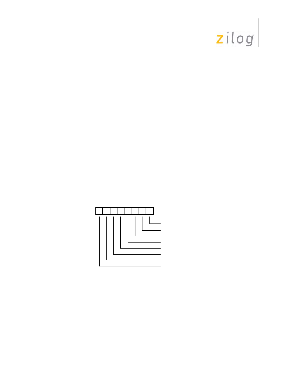
Interrupt Pending Bit
The Interrupt Pending (IP) bit for a given source of interrupt is set by the presence of an interrupt
condition in the SCC. It is reset directly by the processor, or indirectly by some action that the pro-
cessor may take. If the corresponding IE bit is not set, the IP for that source of interrupt will never
be set. The IP bits in the SCC are read only via RR3 as displayed in
.
RR3 Interrupt Pending Bits
Interrupt-Under-Service Bit
The Interrupt-Under-Service (IUS) bits are completely hidden from the processor. An IUS bit is
set during an interrupt acknowledge cycle for the highest priority IP. On the CMOS or ESCC, the
D7 D6 D5 D4 D3 D2 D1 D0
Channel B Ext/Stat
Read Register 3
Channel B Tx IP
Channel B Rx IP
Channel A Ext/Stat
Channel A Tx IP
Channel A Rx IP
0
0
*
Always 0 In B Channel