Zilog Z80230 User Manual
Page 106
SCC/ESCC
User Manual
UM010903-0515
Data Communication Modes
99
In synchronous communications, the bit cell boundaries are referenced to a clock signal common
to both the transmitter and receiver. Consequently, they operate in a fixed phase relationship. This
eliminates the need for the receiver to locate the bit cell boundaries with a clock 16, 32, or 64
times the receive data rate, allowing for higher speed communication links. Some applications
may encode (i.e., NRZI or FM coding) the clock information on the same line as the data. There-
fore, these applications require that the receiver use a high speed clock to find the bit cell boundar-
ies (decoding is typically done with the PLL—Phase-Locked Loop; the SCC has on-chip Digital
PLL). Data encoding eliminates the need to transmit the synchronous clock on a separate wire
from the data.
Synchronous data does not use start and stop bits to delineate the boundaries for each character.
This eliminates the overhead associated with every character and increases the line efficiency.
Because of the phase relationship of synchronous data to a clock, data is transferred in blocks with
no gaps between characters. This requires that there be an agreement as to the location of the char-
acter boundaries so that the characters can be properly framed. This is normally accomplished by
defining special synchronization patterns, or Sync characters. The synchronization pattern serves
as a reference; it signals the receiver that a character boundary occurs immediately after the last bit
of the pattern. For example Monosync Protocol usually uses 16 Hex as this special character, and
the SDLC protocol uses 0, six 1s, followed by a 0 (7E Hex; usually referred to as Flag Pattern) to
mark the beginning and end of a block of data. Another way of identifying the character boundar-
ies (i.e., achieving synchronization) is with a logic signal that goes active just as the first character
is about to enter the receiver. This method is referred to as External Synchronization.
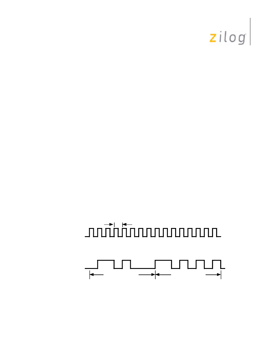
on page 99 displays the character format for synchronous transmission. For example, bits
1-8 might be one character and bits 9-13 part of another character; or, bit 1 might be part of a sec-
ond character, and bits 10-13 part of a third character. This is accomplished by defining a synchro-
nization character, commonly called a Sync Character.
Monosync Data Character Format
Modem Clock
Bit
Bit State
Data LSB
Sync Character
Data Character
1 Bit Time
1 2 3 4 5 6 7 8 9 10 11 12 13 . . .
0 1 1 0 1 0 0 0 1 1 0 1 0 1 0 1